


GRAVITATIONAL WAVES DETECTED 100 YEARS AFTER EINSTEIN'S GENERAL RELATIVITY11 February 2016 -- For the first time, scientists have observed ripples in the fabric of spacetime called gravitational waves, arriving at the earth from a cataclysmic event in the distant universe. This confirms a major prediction of Albert Einstein's 1915 general theory of relativity and opens an unprecedented new window onto the cosmos.
Gravitational waves carry information about their dramatic origins and about the nature of gravity that cannot otherwise be obtained. Physicists have concluded that the detected gravitational waves were produced during the final fraction of a second of the merger of two black holes to produce a single, more massive spinning black hole. This collision of two black holes had been predicted but never observed.
The gravitational waves were detected on September 14, 2015 at 5:51 a.m. Eastern Daylight Time (9:51 a.m. UTC) by both of the twin Laser Interferometer Gravitational-wave Observatory (LIGO) detectors, located in Livingston, Louisiana, and Hanford, Washington, USA. The LIGO Observatories are funded by the National Science Foundation (NSF), and were conceived, built, and are operated by Caltech and MIT. The discovery, accepted for publication in the journal Physical Review Letters, was made by the LIGO Scientific Collaboration (which includes the GEO600 Collaboration and the Australian Consortium for Interferometric Gravitational Astronomy) and the Virgo Collaboration using data from the two LIGO detectors.
Source: http://www.ligo.org/news.php
I've provided a couple of my designs to build your own table top laser interferometer to get a basic understanding of how they work and how sensitive they can be.
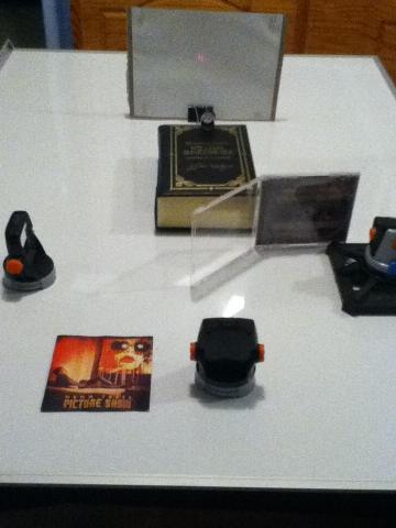
SpyNet Laser Tripwire Laser Interferometer
This is a simple build of a Michelson Interferometer using the SpyNet Laser Tripwire. A few years ago, I accidentally came across this toy and noticed that it has a red laser and two adjustable mirrors. It also has a receiver that will sound an alarm when the laser beam that shines on it is blocked. I had to wait for an after Christmas sale and found a set for 80% off (about $5.00 USD which was less than purchasing a laser pointer and two makeup mirrors). Remember, do not shine the laser beam into your eyes, nor anyone else's.
Parts needs from the Laser Tripwire set:
Laser
2 Adjustable mirrors
Additional Parts:
CD clamshell
Cardboard backing from a 8 ½ X 11 notepad
Sheet of blank white printer paper 8 ½ X 11
4 Paperclips
Large binder clip
A magnifying lens (mine came from my telescope)
Something to prop the lens on (I used my copy of The Complete Works of Shakespeare)
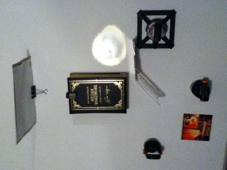
Here’s the layout of the interferometer:
Lego Laser Interferometer
Since it's so easy to build a laser interferometer, I decided to build one for my Lego optics lab.
A table-top interferometer will not be able to detect gravity waves because there is too much noise in the surrounding environment and you need a really big laser interferometer to distinguish between gravitational waves and such mundane things as earthquakes, traffic passing by, or someone dropping a coffee mug in the kitchen. The LIGO, or Laser Interferometer Gravitational-Wave Observatory, is an interferometer whose arms are four kilometers (well-nigh 2.5 miles) long. Using only one interferometer might be able to detect gravitational waves, but multiple interferometers are needed to pinpoint the direction in the sky where the gravity waves are coming from. There are two in the US called LIGO (Livingston, LA and Hanford, WA) and they work with international partner interferometers in Japan (TAMA), Italy (VIRGO), and Germany (GEO).
Einstein predicted gravitational waves in 1916 as a result of general relativity. General relativity describes the curvature of space and time. You can think of space-time as a backyard trampoline. You can roll a marble from one side of the trampoline to the other and because the trampoline surface is held taut and flat, it will roll across in a straight line. Now put a bowling ball in the center of trampoline. The bowling ball will create an indentation in the center of the trampoline and the surface of the trampoline will curve inward toward the bowling ball and most noticeably so near the bowling ball. Now try to roll the marble across the trampoline surface near the bowling ball. The marble’s path will no longer be straight but instead its path will be curved as it rolls across the indentation created by the bowling ball. If you roll the marble a little more slowly, you might actually get it caught in the bowling ball’s “gravitational pull” such that it “orbits” the bowling ball but then quickly spirals into the bowling ball.
Einstein thought of gravitational waves as ripples in space-time. Imagine a pond on a cool spring morning its surface still and glasslike reflecting the crowns of surrounding trees like a mirror. Now throw a stone into the pond. You hear the splash but more importantly, you’ll see circular ripples radiating away from where the stone hit eventually moving across the entire surface of the pond. To make gravitational waves, or ripples in space-time requires big cosmic events. A supernova (a star that explodes), for example, might create detectable gravitational waves.
Unfortunately between 2002 and 2010 LIGO and its international partners were unable to detect gravitational waves. They are hard to detect using ground based interferometers.
The European Space Agency is considering launching a really big space based observatory to detect gravitational waves in 2034. A couple of designs were considered: the Laser Interferometer Space Antenna (LISA) and New Gravitational wave Observatory (NGO), but neither was selected. Nonetheless the future planned gravitational wave observatory might use a laser interferometer since one of the objectives of the LISA Pathfinder is to test how well a laser interferometer will work in deep space. To put things into perspective the three arms of the LISA interferometer were to be set five million kilometers (over three million miles) apart. The Pathfinder interferometer is compact enough to fit in a single spacecraft and rugged enough to withstand the launch aboard a Vega rocket. It’s a small scale test so it won’t be able to detect gravitational waves but is designed to detect the displacement, or movement of two test masses to simulate the components of a vastly larger interferometer. A successful small scale test should start the ball rolling for a full scale space based gravitational wave observatory.
Now that I have the mirrors and lenses from the computer projector I took apart I was able to use the various mechanisms I’ve built so far for my Lego optics lab to build a Lego laser interferometer.
Parts from the old computer projector:
1 Dichroic prism
1 Bi-convex lens
1 Plano-convex lens
2 Mirrors
Lego optics lab mechanisms:
2 Mirror/filter holders
2 Small lens holders
2 Worm Drive pan/tilt mounts with mirrors mounted in the mirror/filter holders
2 LEGO Baseplates 32 x 32
Odds and ends:
1 Snap Circuits Base Grid (11” x 7.7”) # 6SC BG
1 Snap Circuits 9V Holder&Switch (for SCP-03) # 6SC B5
1 Dollar store cat toy (laser pointer) with the guts removed
1 Wall wart adjustable power supply
Even with the fine tuning of worm drive pan/tilt mounts it still takes a bit of time to aim the laser beams to line them up to see the interference patterns and this can drain the batteries on the laser pointer. So, I removed the casing for the laser pointer and connected power to the laser pointer with alligator clips that were connected to the Snap Circuits 9V holder&Switch which was in turn powered by the wall wart adjustable power supply. I don’t recommend doing this for a number of reasons. For this project I had to line up the laser beams and try to photograph the interference patterns which took even longer and the laser started to get dimmer and dimmer. So I had to switch the laser off for bit to give it a rest. When I switched it back on it returned to its original brightness. Using a cat toy laser pointer for an interferometer probably won’t be practical for anything other than demonstration purposes.
I also built a little holder out of Lego for the laser pointer. It turned out that the brass housing for the laser pointer focusing lens fit snugly into the hole in the Lego technic beam (1 X 2). This let me aim the laser pretty near perfectly straight.
For my “Lego Optics Lab: Beam Spliiter” I mounted the dichroic prism on the LEGO turntable with click assembly, and for the “simple pan and tilt mount” I used the standard Lego turntable brick. Since I didn’t need to pan the laser pointer right or left I swapped the turntable bases for both mounts so that the dichroic prism was mounted on the standard turntable mount and the tilt mechanism was mounted on the turntable with click assembly. Then I could tilt the laser pointer up or down yet remain in nearly dead straight alignment with the Lego base plate.
Here’s my Lego Optics Lab: Laser Interferometer setup:

The glass cube with the arrow drawn on top is the dichroic prism. To the right, the bit with the alligator clips connected to it is the laser pointer on the tilt mount. At the bottom of the picture is a worm drive pan/tilt mount with a mirror mounted in the mirror/filter holder. To the left is the other a worm drive pan/tilt mount with a mirror mounted in the mirror/filter holder. To the far left is the Snap Circuits 9V holder&Switch which is in turn powered by the wall wart adjustable power supply. Just above the prism is the small lens holder with the bi-convex lens mounted. Toward the top of the picture is the second small lens holder with the plano-convex lens mounted. At the top of the picture is a white piece of stiff paper that serves as the target where the laser beams combine to display the interference pattern.
When the laser pointer is switched on, the laser beam is split in two at the beam splitter (the dichroic prism). When the beam is split into two, one beam passes straight through the prism to the mirror on the left. The other beam is reflected at 90 degrees and heads for the mirror at the bottom. That beam is reflected off the bottom mirror straight back through the prism, then through the bi-convex lens, then through the plano-convex lens to land on the white paper target magnified quite a bit. The beam that went to the mirror on the left is reflected back through the prism and is split again, one beam going back to the laser pointer and the other beam reflected at 90 degrees and comes out of the prism through the bi-convex lens, then through the plano-convex lens, and lands on the white paper target also magnified quite a bit. Since the two laser beams are combined you can see the interference pattern they create on the target. Here’s a fairly decent picture of the light and dark interference bands on the target:

It was actually a bit difficult to get that shot. The interferometer is fairly sensitive. I could lightly tap my finger on the chair I was sitting on next to the table where I set up the interferometer and see the interference pattern jiggling (both the chair and the table are on a rug on a hardwood floor). I had to remain perfectly still to try to get the shot, but then a car would pass by the house, or one of the cats would walk by, so most of my pictures were shots of the interference bands wobbling and would end up looking like this:

https://dcc.ligo.org/public/0117/T1400762/001/interferometer_2014.pdf


Comments