


Create the MotorA variable in Scratch
(You can create your own Scratch programs here).
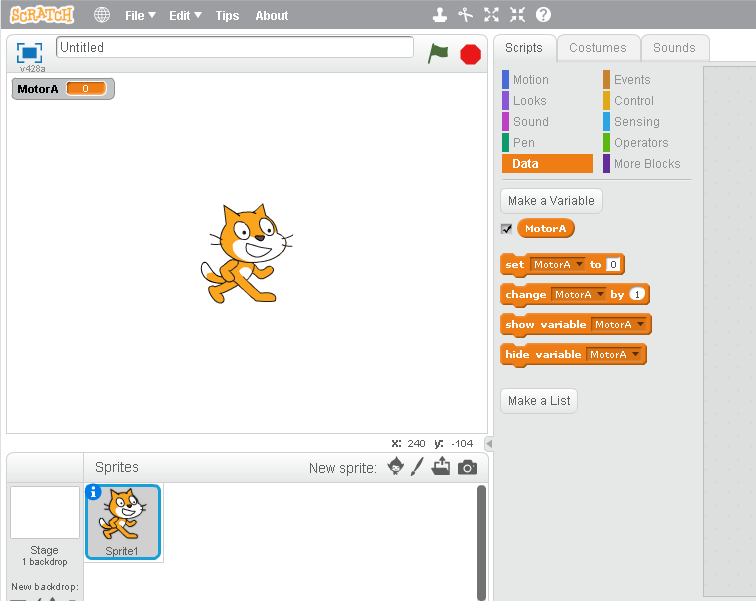
On the Kano, open up the Scratchgpio5 version of Scratch. In the Kano version of Scratch, click on Variables (on the web version click on Data). Click on the “Make a Variable” button and type “MotorA” in the textbox.
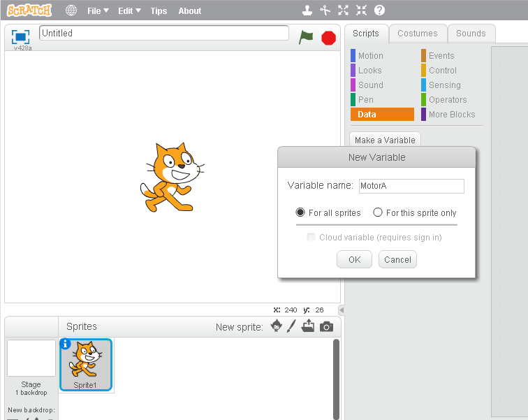
Click the “OK” button and Scratch will create all the motor control variables for you.
The following is the Scratch program I created to control the flashing of an LED:
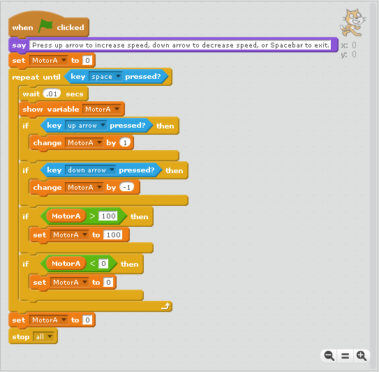
The Scratch program is fairly simple:
WHEN THE GREEN FLAG ICON IS CLICKED
DISPLAY MESSAGE: “Press up arrow to increase speed, down arrow to decrease speed, or spacebar to exit.”
SET MOTOR A TO 0 (Stop motor)
REPEAT
WAIT .01 SECS (Slows processing down enough to display one keypress at a time)
DISPLAY THE SPEED SETTING OF MOTOR A
IF UP ARROW KEY PRESSED
INCREASE MOTOR SPEED BY 1
IF DOWN ARROW KEY PRESSED
DECREASE MOTOR SPEED BY 1
IF MOTOR SPEED IS GREATER THAN 100
SET MOTOR SPEED TO 100
IF MOTOR SPEED IS LESS THAN ZERO
SET MOTOR SPEED TO 0
UNTIL SPACEBAR IS PRESSED
SET MOTOR SPEED TO 0
END PROGRAM
To demonstrate what the Pulse Width Modulation looks like, I decided to connect the Kano Computer to a Snap Circuits LED circuit. I still had the old computer hard disk drive LED connected to the Raspberry Pi pin 9 (Ground) and pin 11 (GPIO17). I also have a header pin to Snap Circuits conversion cable that I made for a Spy Video Trakr hack (you can take a look at the video in my NOTES Section below).

I remove the LED from the Socket and replaced it with a pair of header pins:

Then I connected the header pin to Snap Circuits conversion cable to the header pins:

Raspberry Pi pin 11(GPIO17) is connected to the Snap Circuits 100 Ohm resistor, which is connected to the red LED, and the red LED is connected to the Raspberry Pi pin 9 (ground). When I press the up arrow on the Kano keyboard, the red LED should flash faster. When I press the down arrow the flashing of the red LED should become slower and slower:
Connecting a motor to the Raspberry Pi will require some extra circuitry. I’ll see if I can’t come up with a fairly simple method to power a motor without burning up the Raspberry Pi in a future article. In the meantime you can take a look at this primer on transistors. You are also welcome to follow me on Twitter: @SteveSchuler20
NOTES:
Video of Spy Video Trakr Hack


Comments