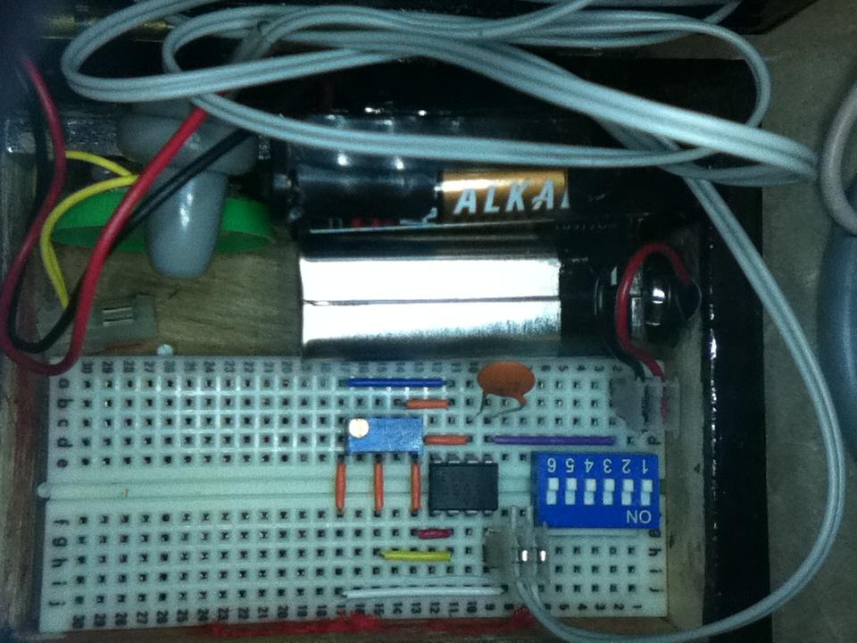
A tone generator is a useful piece of test equipment used, for example, to test the frequency range of audio equipment such as your stereo or the external speakers for your iPod. A tone generator can also be used to tune a musical instrument such as a guitar. You can make a simple tone generator using a 555 Timer IC, a capacitor, potentiometer, speaker, and a power source (circuit pictured above). Here’s the schematic:

If this circuit seems familiar to you, it might be because of this previous blog post. Talkingelectronics.com used my picture and only slightly modified it with digital photo editing software to remove the resistors. They also paraphrased my instructions. But they didn't cite my article as their source. So, I built their version of the 555 “guitar tuner” (again, pictured above) except I added a switch and didn’t connect up pin 4. I tested it and it actually works fairly decently except you can never quite get to a perfect 440 Hz pitch—even with the finely tunable trim pot I used, I can maybe get to 439.9 Hz to 440.1 Hz, but never quite to perfect pitch (it doesn't matter whether or not you connect up pin 4—it still never gets to perfect pitch).
There is a simple method to solve this pitch problem. Even though it is a bit of a kludge (a simple but inelegant solution), it does provide an opportunity to demonstrate how resistors in series work. For this article I’ll demonstrate how to solve the problem using Snap Circuits, but it should be easy to follow along if you have a breadboard and the required components.
For an introduction to the 555 timer and Snap Circuits, see this article. To learn how potentiometers, or variable resistors work, see this article. To learn how capacitors work, see this article. Here’s how to build the 555 tone generator/guitar tuner using Snap Circuits (with a 500k pot instead of a 100k pot):
Parts needed:
555 Timer IC (I used a KIA555p, but the NE555 will do just fine)
Snap Circuits Parts:
1 Base Grid (11” x 7.7”) # 6SC BG
1 Eight-Pin IC Socket # 6SC ?U8
1 0.2uF Capacitor # 6SC C1
1 Adjustable Resistor 500k ohm # 6SC RV3
1 Whistle Chip # 6SC WC
1 4.5 Volt Battery Holder # 6SC B3
1 Slide Switch # 6SC S1
1 Single Snap Conductor # 6SC 01
5 Conductor with 2-snaps # 6SC 02
3 Conductor with 3-snaps # 6SC 03
2 Conductor with 4-snaps # 6SC 04
1 Conductor with 5-snaps # 6SC 05


Switch the circuit on and turn the potentiometer (Adjustable Resistor RV3) to hear the different frequencies the circuit can produce. Here’s a video demonstrating how simple it is to use the Snap Circuits tone generator:
At the end of the video, I swap the trim pot for a Light Dependent Resistor (Photosensitive Resistor RP) turning the circuit into an audible light meter, or optical theremin.
To try to use it this tone generator as a guitar tuner might be a bit difficult because it might be hard to turn the 500k trim pot just slightly enough to hit the 440 Hz pitch—a slight turn of the 500K pot might, say, jump from 430 Hz to 450 Hz and you might not be able to turn it slightly enough to hit the perfect 440 Hz pitch.
To add a bit of fine tuning into the circuit you could install the 50K linear potentiometer (Variable Resistor RV) in series with the 500k pot. Then you can get close to 440 Hz with 500K pot (for example, you’re able to get to 430 Hz with the 500 K pot) and then use the 50K linear (RV) to fine tune it to a perfect 440 Hz pitch.
In this next build I’ll add a couple of extra components to make the circuit a little more functional, but it is still essentially the same kind of circuit.
Parts needed:
555 Timer IC (I used a KIA555p, but the NE555 will do just fine)
Headphones with 3.5mm male jack
Snap Circuits Parts:
1 Base Grid (11” x 7.7”) # 6SC BG
1 Eight-Pin IC Socket # 6SC ?U8
1 0.2uF Capacitor # 6SC C1
1 Adjustable Resistor 500k ohm # 6SC RV3
1 Whistle Chip # 6SC WC
1 4.5 Volt Battery Holder # 6SC B3
1 Slide Switch # 6SC S1
1 SPDT Switch # 6SC S5
1 Audio Jack on Snaps, Horizontal # 6SC JA
2 Single Snap Conductor # 6SC 01
8 Conductor with 2-snaps # 6SC 02
4 Conductor with 3-snaps # 6SC 03
4 Conductor with 4-snaps # 6SC 04
1 Conductor with 5-snaps # 6SC 05


You’ll notice three new additions to the circuit: the 50K linear pot (RV), the single pole double throw switch (S5), and the audio jack. I installed the single pole double throw switch (S5) to be able to switch the output from pin 3 on the 555 timer to either ground or the positive terminal on the battery. When the output from pin 3 is connected to ground, the 555 generates a pulsed output. When the output from pin 3 is connected to the positive terminal of the battery, the 555 produces a square wave output. Unfortunately, you can’t tell the difference in sound of pulsed output and square wave output when you use the piezoelectric speaker, or Whistle Chip (WC). You can tell the difference in sound when you connect up a good pair of headphones which is why I installed the audio jack (and to save my wife’s hearing from all the beeps and whistles from the 555 tone generator circuit). And last, but not least, the 50k linear pot (RV) to fine tune the circuit to the perfect 440 Hz pitch.
If you just use the 50K linear pot (RV) in the circuit by itself, you can’t
quite reach 440 Hz, so the 440 Hz pitch is somewhere between 50K and 100K.If you wanted to find out approximately how much resistance you’d need in the circuit (between pin 3 and pin 6 on the 555 timer), you could replace the 500k pot with individual resistors. Slide the Linear pot all the way to the left (to the side nearest the battery block to set it at 50K). Then install different combinations of single resistors. For example, if I install three 1K resistors in series, I’ll have 53K resistance in the circuit. If I install three 5.1K resistors in series, I’ll have 65.3K resistance in the circuit. If I install two 10K resistors and one 1K resistor, I’ll have 71K resistance in the circuit. And so on.

I was able to install three 10K resistors in the circuit and with only a slight adjustment of the linear pot (RV), I hit the sweet spot of 440Hz. So, in this circuit, to generate a tone of 440 Hz, I needed somewhere in the neighborhood of 80K resistance.
In this example I needed to add 30K of resistance between the linear potentiometer (RV) and pin 3 on the 555 timer, but Snap Circuits does not have a 30K resistor. I instead added three 10K resistors to reach a total of 30K. You’ll probably see the formula written different ways on different websites, but as long as you know how to add you can always remember the formula:
Total Resistance = Resistor 1 + Resistor 2 + Resistor 3…
The ellipsis at the end just means you can keep adding resistors ad infinitum (again and again, forever). So, Total Resistance (30K) equals Resistor 1 (10K) plus Resistor 2 (10k) plus Resistor 3 (10K). And when we add the Total Resistance of 30K in series with 50K resistance of the linear potentiometer (RV), there is a total resistance of 80K between pin 3 and pin 6 of the 555 Timer.
Another benefit of installing the Audio Jack in the circuit is to be able to connect it up to a stereo, iPod speakers, etc. and test them. The device I tested was a Boom Tunes speaker that I found at a store called Five Below for, well, $5.00. I thought it might be interesting to try some experiments vibrating different surfaces. Anyway, I connected the Boom Tunes speaker to the 555 tone generator and stuck the speaker to the microphone on my iPod and opened my iPod oscilloscope app. I was disappointed to find that when I switched between the square wave output and the pulsed output from the 555, I could not tell the difference in sound (like you can with even cheap dollar store headphones) nor could I see the difference on the oscilloscope app.
If you have 3.5mm to 6.35mm (1/4 inch) adapter, you can connect it to a guitar amplifier. In this case rather than testing the frequency range of the guitar amp, I decided to install the Light Dependent Resistor and have a bit of fun with my optical Theremin: