


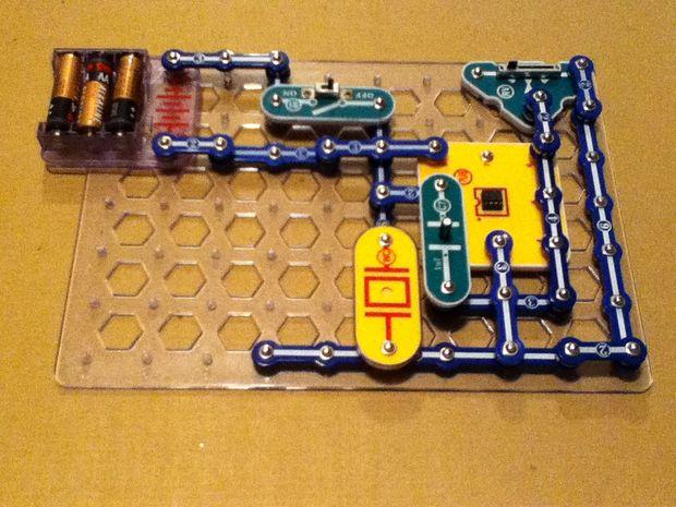
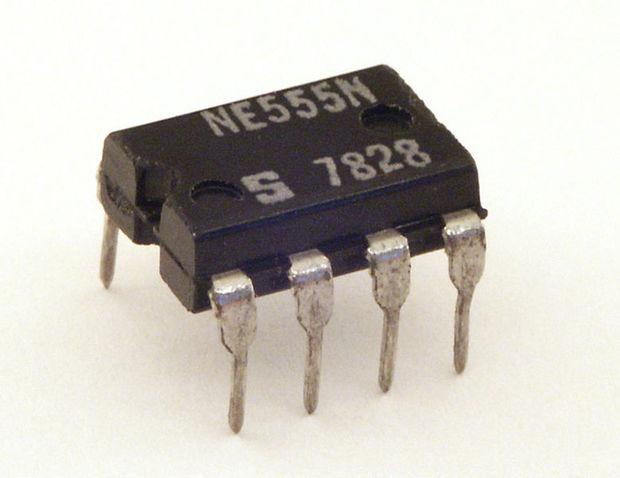
Snap Circuits is an educational toy that teaches electronics with solderless snap-together electronic components. Each component has the schematic symbol and a label printed on its plastic case that is color coded for easy identification. They snap together with ordinary clothing snaps. The components also snap onto a 10 X 7 plastic base grid somewhat analogous to a solderless breadboard. There are several Snap Circuits kits that range from a few simple circuits to the largest kit that includes 750 electronic projects. All the kits include manuals printed in color with instructions for ages 8 or older and with easy to follow diagrams to assemble the projects. The illustrations for each project look almost exactly like what the components will look on the base grid when finished. Because the electronic symbol is printed on each electronic component, once the project is completed, it will look like a printed electronic schematic. The 555 Timer ICThe 555 Timer IC was introduced by a company called Signetics (later bought out by Philips) in 1972 and was designed by Hans R. Camenzind in 1971. The 555 chip has 25 transistors, 15 resistors and 2 diodes in an 8 pin DIP (Dual In-line Package) and looks like a square bug with eight legs. It has a notch at the top and Pin 1 is in the top left corner. (Source)
(Source)
 (Source)The following are the pins of the 555 Timer IC that will be used for this build:Pin 1 is Ground. It is connected to the negative side of your battery along with any other components in your circuit connected to ground.Pin 2 is the Trigger pin. It starts the timing cycle of the 555 if the voltage going to pin 2 falls below 1/3 Vcc (supply voltage, or voltage from the battery) and sets pin 3 high (switches it on).Pin 3 is the Output pin. Have you seen those geeky T-shirts that say "there are only 10 types of people in the world: those who understand binary, and those who don't?" If you find yourself chuckling, then you understand binary. The output of pin 3 is binary. It is either on or it is off. High or low. 1 or 0. When pin 3 is switched on (or set high), it is close to Vcc (supply voltage, or voltage from the battery). When pin 3 is switched off (or set low), 0 volts will be sent out on pin 3.Pin 6 is the Threshold pin. It ends the timing cycle of the 555 if the voltage going to pin 6 reaches 2/3 Vcc (supply voltage, or voltage from the battery) and sets pin 3 low (switches it off).Pin 8 is Vcc (supply voltage, or voltage from the battery). It is connected to the positive side of your battery or power along with any other components in your circuit connected to positive.The breadboard buildFirst I’ll demonstrate how to build the 555 tone generator using conventional electronics and a bread board and then I’ll demonstrate the build using Snap Circuits. I've upgraded from my plastic zinc tablets box to a wooden cork art jewelry box that I tore the guts out of (found it at Goodwill for .50 USD):
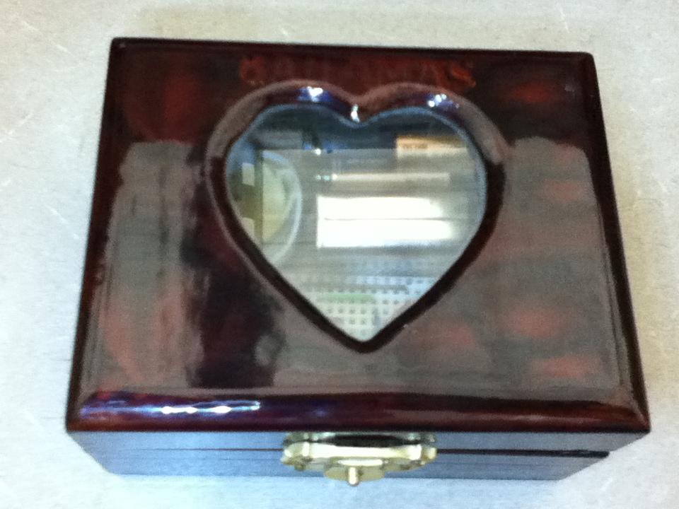 Parts needed:555 Timer IC (I used a KIA555p, but the NE555 will do just fine)
Small Breadboard
Solderless breadboard jumper wire kit
SPST switch
Piezoelectric speaker
0.1uf capacitor
50k potentiometer that can be mounted on a bread board
4.5 volt battery holder (for three AAA bateries)Here’s the schematic:

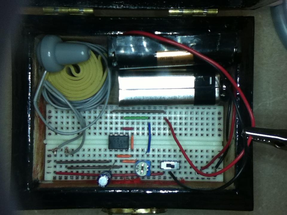
(Circuit design created using Paul Falstad’s Analog Circuit Simulator Applet)Here’s the build:
 The step-by-step Snap Circuits buildParts needed: 555 Timer IC (I used a KIA555p, but the NE555 will do just fine)Snap Circuits Parts: 1Base Grid (11” x 7.7”) # 6SC BG
1 Eight-Pin IC Socket # 6SC ?U8
1 0.1uF Capacitor # 6SC C7
1 Variable Resistor #6SC RV
1 Whistle Chip # 6SC WC
1 4.5 Volt Battery Holder # 6SC B3
1 Slide Switch # 6SC S1
1 Single Snap Conductor # 6SC 01
7 Conductor with 2-snaps # 6SC 02
5 Conductor with 3-snaps # 6SC 03
1 Conductor with 4-snaps # 6SC 04
1 Conductor with 5-snaps # 6SC 05
2 Conductor with 6-snaps # 6SC 05(You can order Snap Circuits parts here.)Insert the 555 timer chip into the Snap Circuits Eight-Pin IC Socket block.

(Source)Make sure that the notch in the top of the 555 timer chip is aligned with the diagram of the chip pictured on the IC socket block.

(Source)Build the circuit shown:
 (You can design your own Snap Circuits by downloading the Snap Circuits Designer from this web page.)
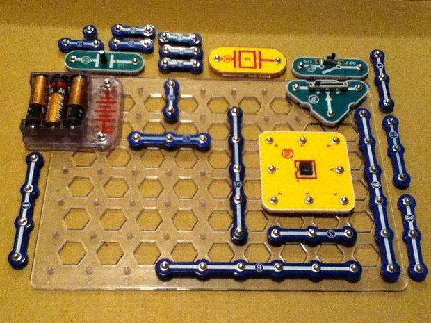

Step 2. The 0.1 uf capacitor charges up.
Step 3. When the charge in the capacitor reaches 2/3 voltage (3 volts), this is detected by pin 6, the Threshold pin, which ends the timing cycle and sets pin 3, the output pin, low (0 volts is sent out on pin 3).
Step 4. The 0.1 uf capacitor discharges.
Step 5. When pin 2, the trigger pin, detects that the capacitor voltage has discharged to 1/3 voltage (1.5 volts) it starts the timing cycle and sets pin 3, the output pin, high (4.5 volts is sent out on pin 3).
This process repeats over and over again until you switch the circuit off. The 555 chip is in astable mode which means that Pin 3 is sending a continuous stream of pulses between 4.5 volts and 0 volts called a square wave signal that can be heard on a speaker as a tone.
This circuit is a simplified version of my 555 Guituner. I must give credit for the idea of connecting the 50k potentiometer from pin 6 to pin 3 to the nice folks over at EEWeb who provided excellent assistance with the development of the Guituner circuit. You can read the discussion thread here.I’ve decided to call the circuit simply “The 555 Test Circuit.” It’s namesake is the “555 ‘Black Box’ Test Circuit” by Forrest M. Mims III (he seems to like naming his circuits, to wit, his Atari Punk Console). Though my circuit is a nonstandard 555 circuit, it serves the same purpose as Forrest’s Black Box test circuit. To borrow a quotation from Forrest:“A Black box circuit is one that’s there when you need it. You can use it even if you don’t know how it works. This ‘Black Box’ test circuit produces a tone with a frequency controlled by a resistor [the 50k potentiometer] and a capacitor. It will help you understand how resistors and capacitors work on their own and together.” (Source: Radio Shack Electronics Learning Lab Workbook 1, By Forrest M. Mims III, p19)To understand how resistance works in the circuit, simply replace the 50k potentiometer with, say, a 100 ohm resistor and then listen to the change in pitch of the tone on the speaker. Then replace the 100 ohm resistor with a 1k resistor and listen to the change in pitch. Then a 5.1k resistor. And so on. If you replace the 50k potentiometer with a photosensitive resistor, or light dependent resistor you’ll have an optical theremin similar to my zinc tablet box optical theremin.Caleb Heath and Nicole Quist over at the American Institute of Physics are using my optical theremin “as the basis for a multi-sensor theremin,” according to Heath, that will be included in their Science Outreach Catalyst Kits . “We can swap the photocell for various other things, like pressure or bend sensors,” said Heath. The kits “contain exploratory physics and science activities specifically designed for SPS Chapters and collegiate physics departments to use in outreach presentations to local elementary, middle and high school students,” according to the SOCKs website. I sent Heath the schematic and design for the circuit in this article since it uses fewer parts and is simpler to build. I think, however, he may be going with a circuit that is actually a "dark detector." According to this blog post Heath wrote: "Prototypes for the SOCK will be going through their first field test, among them an optical Theremin. Usually theremins are majestic instruments. Ours is a beast that screams when it’s dark and quiets down if you hit it with a laser."


Comments