


Build a laser oscilloscope using Lego, littleBits, Erector set, and the Kano Computer. In honor of The International Year of Light I’ll demonstrate how use the Kano computer to drive a littleBits motor with an optical coupler, or optocoupler. An optocoupler, according to Wikipedia, "is a component that transfers electrical signals between two isolated circuits by using light." The Kano Computer is one isolated circuit and the littleBits Light Sensor/Motor is the second isolated circuit. I’ll use the Kano Computer to flash an LED (Light Emitting Diode) and these flashes are read by the littleBits Light Sensor to turn the littleBits motor on and off.
While the LED of the Kano is switched on, the light sensor will switch the motor on and when the LED is switched off the light sensor will switch the motor off. The faster the LED is switched on and off, the faster the motor will spin. Conversely, the slower the LED is switched on and off, the slower the motor will spin.
To get the Kano Computer to flash an LED, you’ll need to install the scratchgpio5 software on the Kano. For detailed instructions see my review of the Kano computer here. Also, if you’re not familiar with littleBits, see my review here.In my review of the Kano Computer, I demonstrated how to use MIT’s Scratch graphical programming language on the Kano to flash an LED (the “Hello World!” program of hardware hacking). I’ll again demonstrate how to flash an LED, but using a special variable in Scratch called “MotorA”. Scratch automatically handles all of the programming for MotorA to produce a “pulse width modulation” (PWM) signal on Pin 11 of the Raspberry Pi. For a primer on pulse width modulation, see this article. I’ll show you how to write a simple program to increase and decrease the flashing of an LED by pressing keys on the Kano keyboard.
Create the MotorA variable in Scratch
(You can create your own Scratch programs here).
On the Kano, open up the Scratchgpio5 version of Scratch. In the Kano version of Scratch, click on Variables (on the web version click on Data). Click on the “Make a Variable” button and type “MotorA” in the textbox.
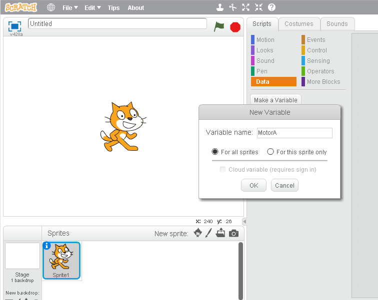
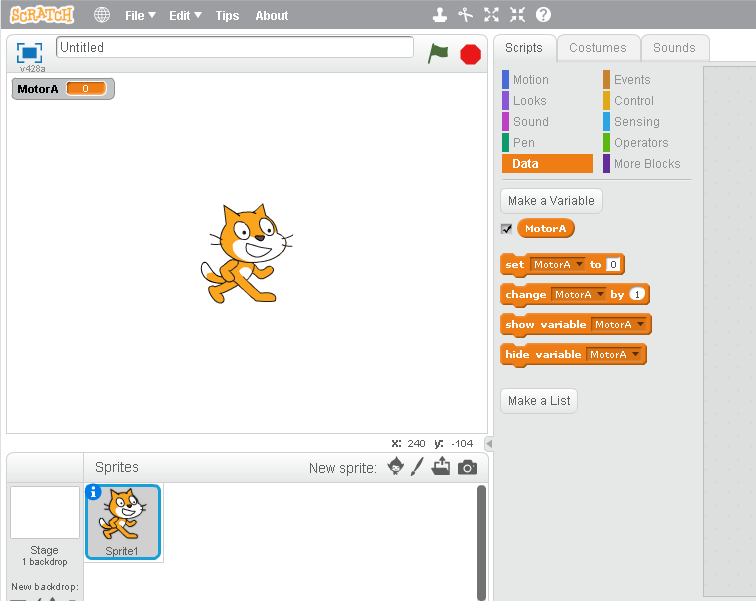
Click the “OK” button and Scratch will create all the motor control variables for you.
The following is the Scratch program I created to control the flashing of an LED:
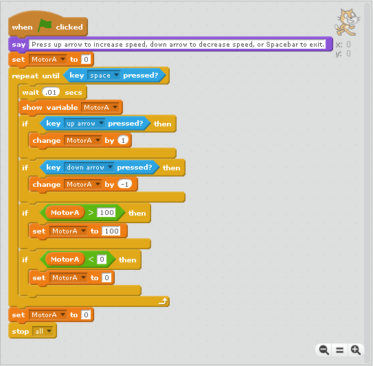
The Scratch program is fairly simple:
WHEN THE GREEN FLAG ICON IS CLICKED
DISPLAY MESSAGE: “Press up arrow to increase speed, down arrow to decrease speed, or spacebar to exit.”
SET MOTOR A TO 0 (Stop motor)
REPEAT
WAIT .01 SECS (Slows processing down enough to display one keypress at a time)
DISPLAY THE SPEED SETTING OF MOTOR A
IF UP ARROW KEY PRESSED
INCREASE MOTOR SPEED BY 1
IF DOWN ARROW KEY PRESSED
DECREASE MOTOR SPEED BY 1
IF MOTOR SPEED IS GREATER THAN 100
SET MOTOR SPEED TO 100
IF MOTOR SPEED IS LESS THAN ZERO
SET MOTOR SPEED TO 0
UNTIL SPACEBAR IS PRESSED
SET MOTOR SPEED TO 0
END PROGRAM
Build the laser mirror spinner
To be able to view the sound wave patterns we’ll need to bounce the laser beam off a spinning mirror and then project the beam on to a screen. Here’s how I built my laser mirror spinner out of Lego and littleBits:


Test the Kano computer and laser spinner
In the following video I have the LED from the Kano computer plugged into the hole in the Lego Technic plate above the LDR (Light Dependent Resistor) on the littleBits light sensor module. When I press the up arrow on the Kano keyboard the LED flashes faster and faster and the light sensor switches the littleBits motor on and off faster and faster—thus the mirror spins faster and faster. When I press the down arrow on the Kano keyboard the LED flashes slower and slower, the light sensor switches the littleBits motor on and off slower, and the mirror spins slower.
Build the laser mount, speaker mount, and graph paper display screen
Now we’ll have to hang the laser and the speaker at about the same level as the spinning mirror (it’s easier to aim the laser at the mirror on the speaker, then at the spinning mirror, and then at the graph paper screen). I used Erector set parts to build stands for the laser and the speaker.
For directions to build the stand for the laser pointer see my article “Erector Set Magnetic Optical Mount For Laser Pointer.”For the speaker I chose to use the Boom Tunes speaker. The Boom Tunes speaker is described on Amazon as:
a compact, lightweight device that turns anything into a speaker that lets you play music around the house, outside, or anywhere you go! Simply plug it into any ipod, music player, or computer and stick the Boom Tunes on a box, table, water bottle or any surface that reflects sound! The bigger the object, the louder the sound. You can turn anything into a speaker- from boxes to cups, to cans, coolers and tables, and even sneakers....almost anything you can think of! The secret is the vibration pod that transfers crystal clear sound with treble and bass to any object. Stick it on almost anything and BOOM...it’s a speaker.”
It was a simple matter to attach a small mirror to the sticky part of the Boom Tunes speaker.


Next I built a chip clip mount for the speaker (simple build instructions can be found here) and I mounted the speaker with the mirror attached:

Build the graph paper screen
The graph paper screen is easy to build with a piece of cardboard, graph paper, and a large binder clip:


All the parts of the LaserOscope together
In the following picture you’ll see all the essential parts of the LaserOscope together (starting from the left): The graph paper screen, Kano computer keyboard, Boom Tunes speaker mounted on Erector set stand, laser pointer mounted on Erector set stand, Kano Computer, Boom Tunes speaker case, laser mirror spinner, and iPod with sine wave generator app loaded. The laser pointer is pointed at the mirror on the Boom Tunes speaker which reflect the laser beam onto the laser spinner mirror which reflect the laser beam on to the graph paper screen.

In order to shoot the following video I had to make two modifications to the original design. I had to attach a wall wart power supply to the littleBits power module so I wouldn't wear out the 9 volt battery, and I powered the Kano computer with a mobile phone battery instead of its normal power supply. Here’s a shot of the Kano powered by the cell phone battery:

And finally here’s the video that demonstrates how the LaserOscope works. As I sweep through various sine wave frequencies you see their wave forms displayed on the graph paper screen:
Follow me on Twitter: @SteveSchuler20


Comments