

I am pleased to be able to publish here in my blog a historical document of some importance: a short history of radar by Sir Robert Watson-Watt. The document - reproduced below these introductory comments - includes some information and images which have not, to the best of my knowledge, been published before on the internet. Of special interest to historians is the
first photographic record of radiolocation of aircraft, made on the 24th of July, 1935.
(A larger image is included within the article, below.) It is also the first record of incidental - as against planned - detection of an aircraft. The plan was to detect a Westland Wallace target plane, probably of the Royal Auxiliary Air Force.
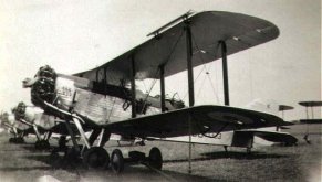
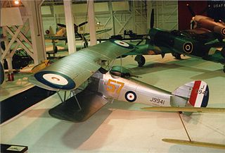
The experimenters also detected three Hawker Harts of the R.A.F. which happened to be within range of this experimental radar installation and which were not part of the experiment as planned.
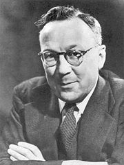
Sir Robert Alexander Watson-Watt, KCB, FRS, FRAeS (13 April 1892 – 5 December 1973)
Images above courtesy Wikimedia Commons.
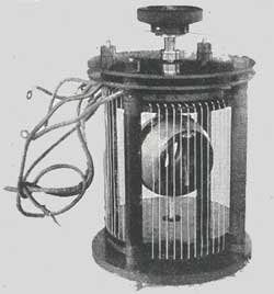
Mentioned in the article, the radiogoniometer, radio-goniometer or radio goniometer consists in essence of two coils of wire, each somewhat like an RDF loop antenna, which can be rotated to find the bearing of a radio signal.
The article by Sir Robert Watson-Watt begins below. For clarity I have reversed the original order of figures 9 and 10, an order which was not problematic in the original printed layout.
Apart from the above-noted change and my addition of hyperlinks and formatting, the article is reproduced verbatim.
From the science magazine Discovery, September 1945.
-----------------------------------------------------------------------------------------------------------------
RADAR - Radio Detection and Ranging - was first known under the cryptic letters "R.D.F.": the term "Radiolocation" came into favour in 1941 after the first public disclosure that we were using this new technique, but this has now been superseded by the word "Radar". The first practical and detailed proposals for locating aircraft by radio were made in 1935 by the author of this article who is now Scientific Adviser on Telecommunications to the Air Ministry and the Ministry of Aircraft Production.
Radar
SIR ROBERT WATSON-WATT, CB., FR.S.
THE greatest difficulties in military operations are to know where and in what strength the enemy is, and what he is going to do next, and to have this information in sufficient time to frustrate his intentions. In mobile warfare there arise difficulties of the same general kind in knowing where you yourself are, and when, if you do certain things, you will arrive at your objective. This general two-fold problem of acquiring and maintaining timely information about the relative positions and rate of change or relative positions of the elements of the two forces has a series of particular cases. These run into greater and greater detail from the general strategic picture to the problem of the weapon aimer, who has to measure or estimate the factors necessary to make his missile occupy the same position, at the same moment, as his target.
The particular problem of the early detection and location of enemy aircraft was thus no new problem when it came up for special attention in the early days of 1935. Many people knew all the difficulties of seeing or hearing aircraft sufficiently early to allow air defence measures to be made effective. The searchlight was an attempt to reduce the uncertainties due to darkness. The acoustic location system was an attempt to use means which were independent of visibility. The searchlight was a poor device because it had not only to search for a needle in a haystack, the range of its search was too short and it had no means of knowing whether it was missing the needle through looking too high, too low, too much to the left or too much to the right. The acoustic system was also very limited in its capabilities because it was subject to meteorological vagaries, because it too was short in effective range (although it could under favourable conditions far outrange the searchlight), and because it was very poor at searching out the information about one aircraft from among the noises due to other aircraft, and from the noises due to steamers and motor cars and the rustling of trees in the wind, and all the other background noises which will go on happening, peace or war.
There was then no fresh need in those first days of 1935, nor did there appear in 1934 any novel means for meeting that need. All the elements of a radio system to meet the need were available well before 1934. Why then did British radar appear in the first months of 1935, as an answer to a long standing military need? There were lots of people who knew the need and lots who had in their minds parts at least of the answer to the need. There were very few people who were in a position to ask the right questions, at the right time, in the right language, or the right people. The revolution of 1935 came because political, military and scientific foresight brought together the people who were qualified to put the question in the right shape, and the people who could put the answer into the right shape, in intimate and continuous contact. As Lord Swinton has recently said:
There was nothing very novel in calling in scientists; it would indeed have been very odd if we had not done so. What I think was important and was perhaps then novel, and was certainly essential, was that these men became from the start an integral and vital part of the Air Staff. They were at the heart, and of the heart, of operational planning and that relationship, intimate, close, was, and I believe always will be, the key to success.
The elements for meeting the new urgent need existed only because a programme of radio research had been followed in this country, and in America. which was not directed towards the immediate provision of bigger and better radio sets but which was probing into the fundamental mechanism of the things that happen to radio waves in their travel about the world and of the interfering waves which prevented the fullest and most convenient use of the waves carrying desired communications. The most important lesson for the future which is to he derived from the history and achievement of radar is not contained in the broadly true and gratifying statements that "It may be claimed that radar saved the civilised world", that "Radar has brought about the greatest revolution in naval tactics since the change from sail to steam", that "Radar has, more than any single development since the airplane, changed the face of warfare."
Importance of Fundamental Research
The really important lesson is that it is far more essential in the national interest in peace and in war that there should be an adequate supply of flexible minds and flexible techniques available in the country than that any great concentration of these minds should be put on to the solution of immediate problems and the provision of immediate equipment. It is more important that there should be a large number of scientists free to nose around in other peoples business, asking their own questions in their own way, than that there should be large establishments engaged on the production of pieces of equipment designed, however ingeniously and economically, to meet operational requirements that have already been formulated. The need was known before 1935; the elements of the solution were also known before 1935. The right mixture of minds was made in the early days of 1935, but there was one other decisive factor.
Those peculiar geographical considerations which contributed to the greatness of
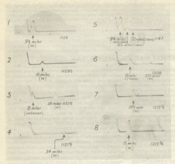
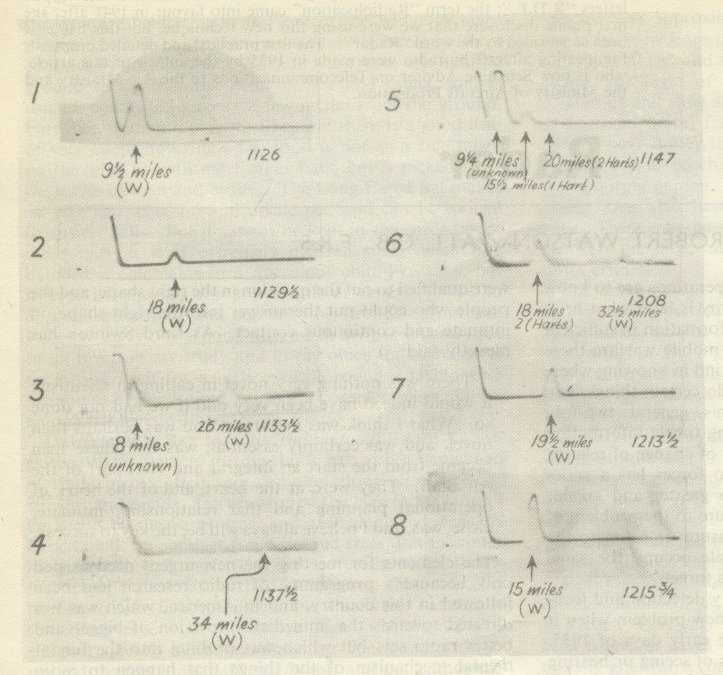
Fig. 1. - The first photographic record of radiolocation of aircraft: made on the 24th July, 1935.
A Wallace aircraft was used as the target. There are 8 separate photographs of the cathode-ray tube trace at moments throughout the period or observation, starting with picture No. 1 taken at 1126 hours and ending with picture No. 8 at 1113¾ hours approximately ¾ hour later.
The time at which each photographic exposure was made is given on the right under each picture. The pictures are numbered consecutively at their left hand extremity.
The "echo" caused by the Wallace aircraft on its outward journey is clearly visible (at increasing distances) in pictures 1 to 4 and on Its return Journey (at decreasing distances) in pictures 6 to 8. The distance (measured by radar) of the Wallace away from the observing station is shown in miles against the corresponding "echo'' in the pictures.
Pictures Nos. 5 and 6 are especially interesting as they indicate a formation of three Hawker Harts which came into radar view uninvited and appeared on the cathode ray tube screen to the surprise of the observers who identified the initial "echo" (not photographed) as a flight of three aircraft, one of which subsequently broke formation and flew off on its own. This was the first radar observation of a flight of several aircraft and the correct interpretation of the "echo" and splitting up of the formation was later confirmed by the pilot of the Wallace, who had himself seer, the evolutions from his own aircraft.
London in peace. made it a peculiarly vulnerable target in war. The magnitude of the British contribution to universal disarmament had enhanced that vulnerability. Quite a number of people had thought of the possibility of a radio system for the detection of aircraft; they had all, so far as can be judged, rejected it on the grounds of impracticability. It required tho peculiar circumstances of 1935 to produce a detailed scientific and technical argument showing that a practicable system could in fact be produced quickly, but that it was a system which would have been ejected on grounds of low engineering efficiency in almost any circumstances. The triumph of the wise men of 1935 was that they proceeded with proposals which were to utilise, in a moment-to-moment military operation, information which would be conveyed by a radio echo that contained not much more than a millionth of a millionth of a millionth of the energy sent out in the hope of getting a usable echo back. Desperate diseases demand optimistic remedies; as it turned out the optimism was thoroughly justified and the remedies proved to be of vastly more general application than were foreseen at the moment of decision.
The first ground radar station for the location of aircraft was set up on that part of the English coast which is nearest to Germany. Work began on May 13 1935. and a notable landmark in its progress is shown in Fig. I. This copy of the photographic record of a test run in which a Wallace aircraft was watched out to 34 miles and picked up on its return trip at 32 miles shows an interesting intrusion into the experiment. Echoes were received from unknown sources between 15 and 20 miles away. These were diagnosed by the scientific observers as coming from a formation of three aircraft, of which one was judged, on the radar evidence alone, as having broken formation and proceeded independently, the other two remaining in close formation. This diagnosis, the first on a formation of aircraft, was confirmed by the pilot of the Wallace on his return. He reported seeing three Harts in a formation from which one detached itself while the other two flew on together.
The method by which this radar information was obtained can be very simply described in relation to the now too familiar analogy with a sound echo. A sharp hand-clap is sent back as an echo by such a reflecting surface as a cliff, and the distance of the cliff from the person making the hand-clap can be estimated by counting seconds until the echo is heard. It takes ten seconds for the soundwave to travel to a cliff a mile away and back again, and sound-seconds can be converted into miles at this rate of exchange. If the hand-clapping is loud the echo from the cliff is proportionately loud, if the clapping is continuous the weak echo may not be heard through the loud and sustained local noise, and if there are several cliffs, each sending back an echo, the echo from any one may be difficult to pick out from the complex of sounds.
So the measurement on a particular cliff is best done by making a very loud and very brief bang, and then allowing a silent interval in which the returning echo stands out clearly. The shorter the bang, too, the less overlapping of echoes from slightly different distances occurs.
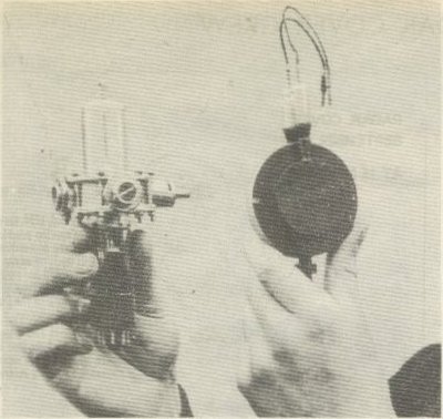
Fig. 2 - The magnetron valve (right), alongside another radar component, the "Sutton" tube.
The radio equivalent of a hand-clap or bang in sound is called a pulse, and almost all practical radar is done by sending out very powerful and very brief pulses, "very powerful" meaning many hundreds of kilowatts and "very brief" meaning a few millionths or a few ten-millionths of a second. The timing of the radio echo has now to be done in millionths of a second, and the rate of exchange is no longer ten seconds (for the double journey out and back) for each mile the echo-producing surface is distant, but ten millionths of a second per mile away. The measuring of millionths of a second is fortunately easy. The cathode ray tube, familiar to the television viewer, depends for its usefulness on the facts that a fine pencil of electrons produce a bright spot on the tube face, and that deflection of the electron beam by electric or magnetic forces can make the spot move, for example, uniformly from left to right in any desired (and reasonable) number of microseconds, stay off right for any other desired number of microseconds, jump back very quickly indeed to its starting-point, and repeat the process at any regular rate desired. Another set of electric or magnetic forces can be made to move the spot vertically, and if they come from a radio receiver into which pulses are fed from a receiving aerial, each pulse will make a V-shaped notch on the horizontal line which, by persistence of fluorescence and persistence of vision, is drawn by the fast-moving spot.
Now we can set up our ground radar system for "early warning of approaching aircraft". We send out powerful pulses at exactly equal intervals (every twenty-fifth of a second if we are going to measure long distances, every five-thousandth of a second for short distances) so that the transmitter is working at a power rating of hundreds of kilowatts or more for about a millionth of a second (a microsecond), is absolutely inactive for the relatively very long time of 40,000 microseconds, then active for a microsecond and so on. We have a big transmitting aerial - a couple of masts 350 feet high are handy supports for it - so arranged that it lets the pulse spread out nearly uniformly over a wide sector in front of the station, but lets very little spread behind, this to avoid confusion with inland aircraft.
A hundred yards or so away we put up a receiving aerial - a 250-foot timber tower is a good thing to put it on - and let it feed the radio receiver connected to our cathode ray tube. Every time a pulse starts out from the transmitter we let the spot on the tube start its left-to-right travel, and the big bang in the receiver due to the wave from a hundred yards away makes a big notch - called a "blip" by the RAF operator, a "break" by the A.A. gunnery operator, a "pip" by the U.S.A. operator - at this left-hand starting end of the horizontal line. Since the line is redrawing itself in exactly the same rhythm as the pulses go out, the blips due to successive pulses are superposed and make a stationary notch. An echo-pulse coming back from an aircraft will arrive later by 10 microseconds for every mile the aircraft is away from the radar station and will make a blip beginning at the point on the horizontal line reached by the bright spot after it has been travelling that number of microseconds. So an aircraft echo makes a slowly moving notch whose left-hand edge reads the distance of the aircraft on the horizontal scale, which we graduate in miles by putting a one-mile graduation for every ten-microseconds left to right travel of the spot.
Thus in Fig. I (v) the spot had travelled for 92 microseconds (from its simultaneous start with the outgoing pulse) before the first echo arrived, 155 microseconds before the first Hart echo came in, and 200 microseconds before that from the two Harts came in This was all repeated twenty-five times a second, and each blip was nearly superposed on its predecessor for the same echo, so that each aircraft was represented by a blip travelling slowly along the range scale at a rate corresponding to its rate of approach to the station.
This explanation has taken many more microseconds than the whole process described, but the rest is easy. We have found the "slant range" to the aircraft. We need to know its bearing from true North, and its flying height, before we have located it in space. To get the bearing we use a special receiving aerial with one set of horizontal wires pointing due North and South, one set due East and West, and a radiogoniometer in which, by turning a handle, we turn a coil which finds out the proportions of signal in the NS and EW wires. When the coil is pointing directly to the compass bearing of the aircraft, the blip is at its biggest; when it is at right angles to that bearing the blip disappears, and this disappearance gives a very accurate measure of the bearing. Note, then, that we can get a bearing on each blip without confusing it with any other or losing sight of any other. The range and bearing for each echo are unmistakably associated; we cannot by mistake take a range on aircraft A and a bearing on aircraft B and thus plot a ghost aircraft at C!
We still have to measure height. The echo from the aircraft reaches an elevated receiving aerial by two routes, one direct and one after reflection at the ground - which acts as a nearly perfect "radio mirror". But in the reflection process a phase-change of very nearly 180o takes place, which means that each peak in the incident wave is almost exactly replaced by a trough in the reflected wave.
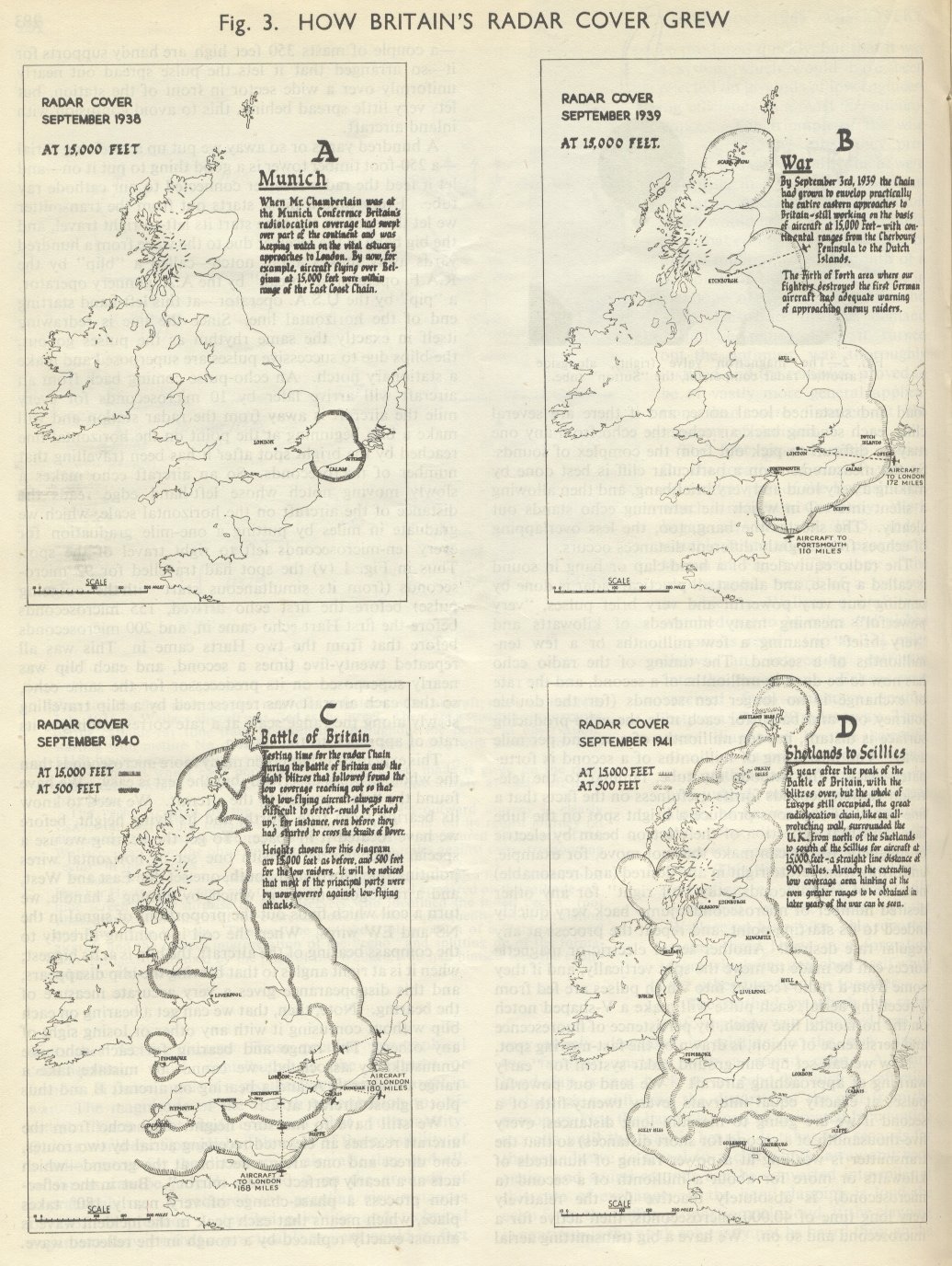
Fig. 3 How Britain's radar cover grew
The direct and reflected waves combine to a resultant wave in which they cancel one another out for grazing incidence and reinforce only at higher angles. So a low-flying aircraft gives an extremely weak signal in a low receiving aerial, a better signal in a higher aerial, and in fact a signal which, for low angles of elevation, is proportional to the square of the product of the aerial height and the flying height. So we can measure the flying height by having two receiving aerials at different heights, and comparing the signals in them by switching on to these two aerials the radiogoniometer which we have just used for measuring bearing.
Fig. 4 - A CH (Chain Home) station.
Now let us sit back and reflect how clever we have all been. We have "floodlit" by radar a vast volume of air in front of our station. An aircraft at 10,000 feet 100 miles away will send us back perhaps a thousandth of a millionth of a millionth of the energy contained in each pulse we send out. People who don't know all about the game will say that we did the floodlighting because in 1935 we hadn't the means of making a powerful radio searchlight. But while it is true that we hadn't, we insisted on floodlighting anyway, and kept it after the radio search-light came. This was because the first and vital need was for a general watch all the time over all our coastline.
We did not want to lose sight of other formations while we were locating one particular formation. Having set up a chain of stations to give us this general cover, which is shown in Fig.3 A. B. C and D, we took a second step which is also represented in Fig. 3 C and D. But to go on with our stock-taking. From our one-trillionth-scale echo we have discovered the distance to a single aircraft at one or two hundred miles with an accuracy of round about one mile. We have measured the bearing of the aircraft which is at that particular range with an accuracy at 100 miles of perhaps ±2o and we have measured its flying height after it has come into about 60 miles distance with an accuracy of perhaps ±1,500 feet. But how did we know about the two and the three Harts in formation, and what could we say about much bigger formations? Well, we knew that there were two aircraft close together because the size of the blip varied comparatively slowly between zero (which is very nearly reached in Fig. 1 (v)) and twice the average (roughly attained in Fig. I (vi)). We knew when there were three aircraft close together because this beating between the two echoes as they passed in and out of phase with one another was rather more rapid and did not cause the blip to fall to zero. As the art of radar progressed our observers, and in particular the W.A.AF. observers who carried the greatest burden of the coastal watch throughout the Battle of Britain, were able to estimate the number of aircraft in formation up to 100 or 150 with an accuracy of some ±10% in numbers. This was attained by close study and wide experience of the complicated echo pattern given by large formations.
All this information for all the formations in sight has to be passed clearly and accurately to a filter centre which is receiving corresponding information from all the stations along a considerable length of coast. But the information is more conveniently given in the form of map reference rather than a distance and bearing from any one of the observing stations. Moreover, the measurement of flying height requires correction because of the departure from absolute uniformity of s!ope of the ground in front of the radar station.
Calibration flights establish what these corrections must be, and the very ingenious electrical calculator which is affectionately, if irreverently, called the "fruit machine" by the radar operators automatically makes these conversions and corrections and displays illuminated figures which are read over the telling line to the filter room.
Fig. 5 - A CH L (Chain Home, Low) station for detecting and reporting low-flying aircraft.
Fig. 6 - Height-finding component of modern centimetric mobile ground radar set.
Fig. 7 - Plan position finding component of modern centrirnetric mobile ground set.
Fig. 8 - A GCI aerial.
Now what about the second step? Earlier it was indicated why low-flying aircraft can creep close inshore before being located. The echo strength, which we have described as being proportional to the square of the product of the aerial height and of the flying height, is also inversely proportional to the square of the wavelength. neglecting other wavelength effects which are of secondary importance. To get long ranges on low-flying aircraft, we have to reduce our wavelengths; this reduction of wavelength allows us to use smaller aerials and we can now rotate these aerials about a vertical axis, so getting a limited kind of radio searchlight. This is the CHL equipment (Fig. 5) which was introduced along the coast in the earliest months of the war to supplement the higher-angle cover given by the big CH stations (Fig. 4); the coverage at 500 feet shown in Fig. 3 C and D is that added by the CHL component of the overall system.
We have to look next at the problems which arose from the fact that even in those early days we had a modest proportion of aircraft of our own to look at along with the enemy aircraft. We wanted, then, some means of discriminating between friend and foe. This, was done by fitting to each of the friendly aircraft a comparatively small IFF set which, on receiving the radar pulses, sent back without any appreciable delay a magnified and coded version of them, thus saying "I am a friend", and through changes in the coding, "I am a particular kind of friend".
The Plan Position Indicator
This roughly was the group of equipments - CH, CHL and IFF - which made their contribution to victory in the day Battle of Britain. They were not, however, sufficient to assure success in the night battle. The accuracies of location attained were good enough to bring the intercepting fighter within visual range by day but not within the very much smaller range of vision at night. There had been under development, since quite early in the history of British radar, the AI system in which the complete radar system, transmitter and receiver, was brought down to such a size that it could be carried in the individual night fighter. This, however, was limited in its effective pick-up range to something between 2½ and 4 miles, and an intermediary was needed to bring the night fighter well within these ranges of his quarry before he took over the responsibility of guiding himself into visual contact by the use or his AI set. The intermediary equipment called GCI (Ground Control of Interception) is attained by adding to he CHL set one of the most revolutionary and versatile devices of all radar, namely, the Plan Position Indicator (PPI).
Instead of starting our range scale at the left-hand side of the tube face we can start it at the centre of the face, and we can make it rotate about that centre in exact unison with the rotation of the CHL aerial system which is now projecting a beam roughly some12o or 15o wide. If, further, we abandon the arrangement of letting the blip appear as a notch on the range scale but instead, by a quite well known method used in television, use the incoming signal to brighten the spot, then it will be seen that we have a system in which the echo is now represented by a bright spot whose position represents in polar co-ordinates the position of the target aircraft on the map - hence the name Plan Position Indicator. The name is not wholly accurate since the measured range is a slant range and not its horizontal projection, but the difference, save at very close ranges, is negligibly small.
It will be clear that since the radio beam is still somewhat wide it would be wrong to think of the bright area corresponding to any particular echo as being really a spot; it is, in fact, a sector of light quite narrow in the radial direction but covering the greater part of the beam width. The bearing of the echo-producing target can, however, be estimated with considerable accuracy by taking the central point of this sector, while its distance is given very accurately by the inner edge of the bright sector. It was with this combination of the CH/CHL on the coast, the GCI set inland and the AI installation in the night fighter itself that the night Battle of Britain was successfully fought in the early months of 1941 and brought to its highly successful conclusion in May of that year. The PPI will appear later in this survey, alike in ground station, shipborne and airborne applications.
There was developed in parallel with the AI set a somewhat similar equipment to be used principally by the aircraft of Coastal Command and of the Naval Air Arm in searching for surface vessels, and in particular for U-boats on the surface, at night or in the presence of mist or low cloud. Even when surface visibility was good there was obviously great advantage to he derived from the ability to shadow a surface ship from an aircraft which could screen itself in cloud cover. The measurement of the slant distance to the surface target was done by the process already described in relation to ground stations, while the relative bearing of the target was measured by the overlapping beam technique which finds application in the CHL and GCI sets already mentioned, in the ground sets for the laying of anti-aircraft and other guns, in "Elsie", the SLC set which allows the searchlight to open directly on its target, and in many forms of shipborne radar.
Fig. 10 Radar "map" of the SW. tip of Wales made by photographing the image thrown on the cathode ray tube of an H2S apparatus in a night-flying aircraft. Nothing has been added to the photograph except the thin outline emphasising the actual coast, and the names. The inlet is that in which Milford Haven and Pembroke are the principal towns.
It was indicated in the first paragraphs of this general survey that the optical searchlight suffered from the grave limitation that once the target is out of the beam of light there is insufficient guidance as to the direction in which the beam must be turned to pick up the target. The overlapping radio beam technique completely eliminates this difficulty. It is comparatively easy to swing a radio beam by a few degrees so that at one moment it is pointing a little to the left of its average position and an instant later an equal amount to the right of that position.
Fig. 9 shows how the echo from a particular target varies during such a switching cycle and how accurately its bearing can be determined if it is on the crossing point of the two overlapping beams, a condition which is indicated by equality of the two echoes, which can be separately displayed. as shown in Fig 9 (ii). The ASV-equipped aircraft can thus have its heading constantly directed on to the surface vessel to be followed or attacked. Despite complications due to drift in cross winds, visual contact with a U-boat at night can be assured when the radar equipment is supplemented by the particular kind of airborne search-light called the "Leigh Light".
Fig. 9

This was the combination of devices which ended the first phase of the Battle of the Atlantic. It was, however, defeated, in accordance with our expectations, by the fitting in the U-boats of radio receiving equipment which allowed the U-boat to submerge before the pursuing aircraft could attack it. Fortunately, plans to meet this enemy counter-action were well advanced before it was applied, and the second phase of the battle will be mentioned when we come to discussion of centimetric radar.
The general principles already outlined need not be traced in their detailed application to the shipborne sets for early warning of impending aircraft attack, to the aids to anti-aircraft gunnery and searchlight laying just mentioned and to the mobile early warning sets which were widely distributed over vulnerable parts of our long lines of communication and battle theatres in the early stages of the war. All of them suffered in greater or less degree from disadvantages and limitations due to the width of the radio beam and the consequent too general illumination, if we may carry over from optics to radio that convenient word which we have already implied in using the terms "radio flood-lighting" and "radio search-light". The main difficulties due to the width of the beam were of three kinds. The indications on an isolated target were not very accurately readable, because they were in effect painted in with a coarse brush. The indications from closely adjacent targets could not be adequately separated, because the coarse-brush smudges corresponding to each overlapped unnecessarily. And since the ground, whether land or sea, is a good reflector of radio waves, echoes from the ground over a considerable area put additional overlaying smudges onto the already somewhat confused picture. It will be clear from what has already been said that there were ways in which flood-lighting and wide-beam illumination were convenient, but there was a long felt and increasingly insistent need for a system in which a really fine pencil of radiation swept systematically, point by point, over the area to be searched, so that only the objects in a very small block sent back echoes at any one instant. Then if we could repeat this systematic point-by-point scanning sufficiently rapidly, the correspondingly fine brush of our electron beam in the cathode ray tube would keep on painting and repainting a sharp and non-smudgy picture showing the plan positions of the reflecting objects.
Centimetric Radar
These needs would be met only by much shorter wave-lengths, because there was no way in which fine radio beams could be produced except by aerials and radio mirrors many wavelengths in aperture, and only if the wavelength were brought down to ten centimetres or less could mirrors of sufficient aperture (measured in wavelengths) be carried in aircraft or even in mobile ship and shore equipments. The demand for high pulse-powers and high receiver sensitivities on centimetric wavelengths had to be met.
It could only be met by that zeal which is born of personal conviction that the need is real and pressing, combined with the knowledge and ingenuity of the physicist-researcher, It was met in this case because, under the growing menace of war in prospect, the small pre-l939 band of radar workers was in the spring of 1939 greatly reinforced. Some ninety of our most brilliant younger physicists were invited to study radar at work in the coastal chain, to discover its needs and to prescribe solutions. They were immediately impressed by the urgency of the centimetric-wave need, and in particular the gifted team which Professor M. L. E. Oliphant had gathered about him at Birmingham University undertook the task or providing a valve to generate power far in excess of anything hitherto attained on centimetric wavelengths. Randall produced the modern magnetron by applying to the older magnetron the newer resonant-cavity technique; others - all, like Professor Oliphant, Professor J. T. Randall and their colleagues working under the general aegis of the Admiralty, to whom had been confided responsibility for valve development for all services - produced novel receiving valves to match, and centimetric radar was ready to revolutionise most of the applications of this highly versatile art of radiolocation.
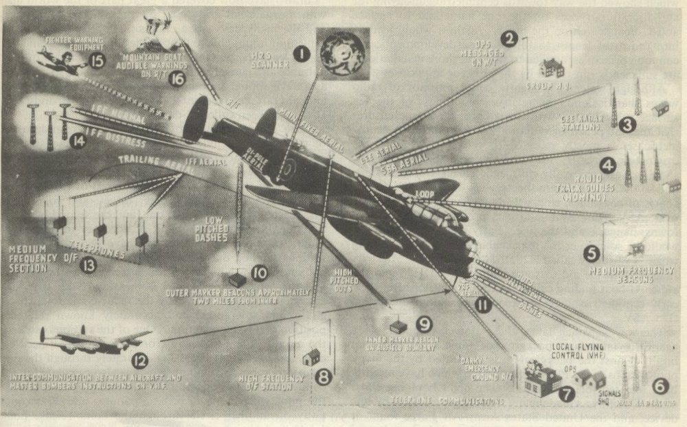
RADAR DEVlCES IN A LANCASTER. A fully equipped plane had 40-50 radio "boxes" using more than 300 valves. This diagram indicates how many navigational aids radar provides.
(I) H2S scanner, housed in a blister below the RAF roundel. (2) Wireless telegraphy link with Group H.Q. (3) "Gee"system of navigations, based on information from a series of ground stations. 4) As homing bomber approaches coast, radio track guides (using Standard Beam Approach aerial) assist navigator. (5) Medium frequency beacons provide direction-finding facilities, using loop aerial inside plane. (6) Main Beam Approach beacons give steady signal tone if pilot is on correct line of approach to aerodrome; too far to port, he hears series of Morse dots, too far to starboard series of dashes. (7) Airfield signals operations arid flying control are all linked by 'phone with (8) the airfield's high-frequency D/F station, Flying Control has a V.H .F. link with aerial (11); and a "Darky" or emergency radio-telephone ink to the ordinary R/T aerial, if all other radio aids fail.
(9) and (10) the inner marker beacon on the aerodrome boundary, and outer marker beacons 2 miles away give pilot his distance from runway in final stages of a beam approach, using di-pole aerial. (12) VHF communication with other aircraft.
(13) Medium frequency D/F stations, which are widely spaced, up to 6700 miles apart. The aircraft uses trailing aerial wound off a drum. (14) IFF - Identification Friend or Foe - system with special aerial. IFF distress version is used by aircraft in difficulties to call the ground stations attention. (15) Fighter warning equipment, warns bomber crew against aerial attack. (16) "Mountain Goat" device gives audible warning of nearby mountains; ground installations need to be erected on the mountains.
The first concentrated drive for centimetric waves had come from those concerned with AI sets. The effect of echoes from the ground in the older one and a half metre sets had been to obscure any aircraft echo coming from a distance greater than the flying height of the night fighter, since echoes poured in from ground at all distances in excess of that of the nearest ground - that vertically below. It was therefore natural that the first centimetric radar set to be produced was an AI set with an ingenious mechanical scanning system which greatly reduced the ground-echo troubles and greatly enhanced the accuracy of location of the bomber by the intercepting fighter. This new equipment, since the first model took to the air in February 1941, did not have so many "customers'' to deal with as its.predecessors, but it did invaluable work at home, in North Africa and the Mediterranean, and in the liberation of Europe.
The experimental AI sets were immediately turned over towards development of the centrimetric ASV which should defeat the expected U-boat listening sets, not yet fitted. Between March 1943 and the end of June the use or something between fifty and a hundred centimetric ASV sets, with their airborne PPI display system, saw the end of the U-boat menace; the combination or ASV- equipped aircraft (in Coastal Command and Naval Air Arm) and radar-equipped surface vessels, destroyers and corvettes in particular, brought what the Führer optimistically called a "temporary setback to our U-boats ... due to one single technical invention of our enemies." The recovery from the "temporary" setback was not achieved before the final defeat of Germany.
The radar sets for destroyer and corvette developed from a laboratory model of ground centrimetric radar which showed the way towards centimetric gun-laying for anti-aircraft purposes on the one hand and to surface anti-U-boat search on the other. Again it would lead us into too great length to follow these developments; the common principles, applied to ship and shore installations, are sufficiently illustrated by the airborne applications.
Although water is a slightly better reflector of radio waves than is land, the relative smoothness of the sea surface as compared with the average landscape ensures that the fine pencil of radiation from an airborne centrimetric set is mostly reflected specularly away from the originating aircraft; little is scattered back. But the shoreline, and especially cliffs, reflect back to the aircraft, and so the PPI picture in the ASV set draws rough outline charts of coastlines, emphasising cliffs and inlets. Moreover ASV flying over land gets prominent echoes from towns, hangars, and the like. Early recognition that this would be so gave us the remarkable aid to night bombing which is variously called H2S, the "gen box" or "Mickey". Indeed, both the aid to town-finding called H2S and the aid to U-boat finding called ASV were developed in their early centimetric stages as a common equipment called H2S/ASV.
The way in which lakes and waterways appear black against a faint land background, while cities show up bright against the background, is illustrated by the many photographs of the PPI display in H2S which have recently been released for publication. The night bombing effort of the R.A.F. was made many times more effective by this device, and the United States Army Air Force found it possible to multiply by a similar factor the number of days on which they could bomb effectively in European weather, with its characteristic long spells when bombing through overcast alone could be practised (Fig. 10).
Meanwhile, other aids to the bomber offensive had grown out from the original radar stem. One of them, the "Gee'' system, which was the most widely installed of all radar systems, did not depend on radar echoes at all, but it used pulses and all the associated techniques which are the essential features of radar, and "Gee" is thus indubitably a radar system. Without "Gee" the thousand-bomber raid, and, far more important, the very close concentration of night bombers in space and time over their target, of which the thousand-bomber raid was a crude precursor, could not have been achieved.
If we send out pulses simultaneously from two ground stations, an aircraft fitted with a pulse-receiver cannot measure his distance from one or the other, because he has no way of knowing when the pulse started out on its journey. But he can measure how much later the one arrives than the other, and thus how much farther away B is than A. He can, in fact, discover on which of a whole family of curves of equal time-difference and thus of equal distance-difference (hyperbolas) he is. And if a third station C also sends out synchronised pulses he can find on which of another set of hyperbolas he is, and so where he is on the map. "Gee" and its American brother "loran'' have now covered a great part of the world map With navigational aids used by aircraft and ships alike and the many days when clouds make it difficult, inconvenient or impossible to "shoot the sun" (or stars) and one has to leave the sextant in its case have lost much of their nuisance and danger value. Gee has become so universal as a navigational aid, and was so valuable to all the ships and aircraft engaged in the assault on Normandy that D-day has been called G-day. "Gee'' gives accuracies of a few miles square at distances of three hundred miles or so from the ground stations, and about a quarter-mile square near the mid-point of the line joining two ground stations. But this satisfies neither the pride of the radar man nor the need of the precision bomber attacking a "pin-point" target: and so, for the first reason, which is a good one, and the second, which is a better, "Oboe", the summit of accuracy in long-range radar, was born. Here, too, we have two ground radar stations sending out pulses, but the pulses are picked up and returned by a highly refined descendant of the IFF set , and the total time of travel is measured with that high accuracy that is permitted by the relative comfort, space-and-weight tolerances, and accurately known reference position of a ground station. One of the stations can keep the aircraft flying (manually, or automatically if need be) on a sector of a circle passing accurately through the prescribed bomb-release point (which is also calculated in the comfort of the ground station) while the other can warn the pilot when he is 8, 6, 4, 2 minutes and 30 seconds away on another circle through the bomb-release point (each circle being, of course, a line of constant distance from the station concerned) and can, if need be, release the bombs automatically from the bomb-rack of an aircraft whose position he knows far more accurately than do its occupants. Errors of about 200 yards in combat conditions and a few tens of yards in practice-range conditions can be attained at distances near 200 miles, and it is satisfactory to record that the Ordnance Survey and its German counterpart agreed so well within this accuracy as to facilitate Oboe operation It is not too much to claim that the Battle of the Ruhr was won by this most spectacular of radar devices.
Even in war radar was far from being solely an instrument of destruction, superlatively though it filled that unpleasantly essential role. For its range of aids to navigation, by radar beacons on the IFF principle guiding the returning flyer home to "Mother", by tracking the "lost" training or operational aircraft within the coverage of the coastal and inland stations, thus making possible radio instructions about the course to set towards safety, by watching coastal shipping groping past minefields arid marine hazards in fog, by eliminating fog and ice hazards on the high seas - an iceberg ten miles away, a growler three miles away announce themselves on the PPI - in a multiplicity of such ways radar is well set on its own course towards safety of sea and air travel in the peace.
_________________________________________________________
End of original article.
Please do advise if you spot an obvious transcription error in Sir Robert's article.
More articles in The Chatter Box


Comments