


The diode is the simplest semiconductor electronic component, but the physics of how they work is perhaps somewhat complicated. There are many resources available on the web such as the Edison Tech Center semiconductor resource page.

Diodes can be made from household items such as a point contact diode made from a razor blade and a pencil used in a foxhole radio. You can also make a diode out of a mason jar, baking soda, aluminum, and copper strips. The razor blade and pencil diode can be difficult to use since making the proper contact can be quite fiddly.
The Mason jar rectifier seems, well, downright dangerous since you plug it directly into an AC outlet. You can, however, use an LED to investigate (much more safely) how a diode lets current flow in only one direction as I demonstrate in this article.
Light Emitting Diodes (LEDs) are ubiquitous. They let you know when your stereo is switched on as well as many devices and appliances in your home. LEDs are found in your digital clock and many other devices that use seven segment displays to form numbers, letters, and characters on the microwave in your kitchen or the equipment in your lab. There’s an infrared LED that helps you channel surf on your LED flat panel TV. They’re in the Jumbotron at the ball game and in electronic billboards. They’re in traffic lights, vehicle lights; just about any incandescent light can now be replaced with an LED.
You can take a look at how an LED is designed and even use and interactive flash player tutorial on how and LED emits light on this web page. You can also adjust the slider on the wavelength selector to change the color of light the LED emits. Different materials can be added to the p-n junctions of LEDs so they can emit different wavelengths of light. For example, add silicon carbide and the LED will emit blue light. LEDs can be manufactured to emit infrared as in your TV remote, ultraviolet (see this article for a demonstration of some uses for UV LEDs) and all the visible light colors in between. The LED is a rather versatile electronic component.
What many people might not know, though, is that the LED can be used as a sensor or input device. For your TV remote to communicate with your TV, when you press the button labeled “1” on your remote, the infrared LED is programmed to flash a series of pulses. There is a photodiode in your TV that senses these pulses or flashes of infrared light by converting the light into voltage or current (another photodiode you’re probably more familiar with is the solar cell that converts sunlight into energy to power your solar garden lights). A microcontroller in your TV reads these pulses (changes in voltage or current) and performs whatever function it is programmed to do when you press the button labeled “1” on your remote—such as change to channel one.
A photodiode and a light emitting diode are similar except that a photodiode is manufactured to more efficiently focus the incoming light on to the photosensitive area of the device. Conversely, the lens of an LED magnifies and focuses the light emitted by the diode (you may notice that the LED seems brighter when you look directly at the lens but not as bright when you look at the LED from an angle). Nonetheless, you can think of a LED as a miniature solar cell that converts light into energy.
Using LEDs as sensors has some advantages. They are much cheaper than photodiodes. They can reduce the number of components needed to build your circuit. That is, the same LED, for example, can function as a light sensor, and an indicator light in your circuit.
A couple things to keep in mind if you are going to use LEDs as sensors: LEDs are not optimized as sensors like photodiodes, so in some cases you may need to modify the LED such as sanding off the lens. LEDs tend to be sensitive to the wavelength of light shining on them. In the following video I have a Snap Circuits yellow LED connected to a Snap Circuits meter. When I shine the red laser on the LED, the meter doesn’t measure any voltage. When I shine the green laser on the LED, the meter measures about 2 volts. I used lasers because lasers are cool and the needle on the meter would deflect better for video.
When deciding on which LEDs to use, obviously test the LEDs you already have. Connect them to a multimeter and shine a light on them to see if you can get a measurement on your meter. Try using a green LED as the light source and green LED as the sensor. Try a red LED as light source and a red LED as the sensor. Or test one color LED as the sensor with different colored LEDs as the light source. Use trial and error to find the best combination Of LEDs.
Forrest Mims III originally wrote about using LEDs a sensors as far back the 1970s, but you can refer to one of his more recent articles published in Make magazine that may shed some light on the subject. Also, for an introduction to the photoelectric effect, that a look at this University of Colorado Boulder web page .
CU-Boulder has also created the following photoelectric effect Java app:
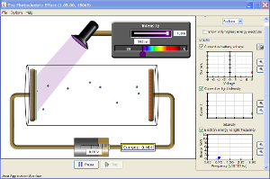


Comments