


This series of pulses can be used to generate a tone that can be used as an alarm or can be adjusted with a fair amount of precision such that it can be used to tune a musical instrument.
I also touched upon the concept of On-Off Keying (OOK) a method of digital modulation used in optical communication such as IrDA.

Next, we’ll take a look at a signal that can be generated by the 555 test circuit when we connect the output pin (pin 3) to positive (+). When pin 3 is connected to positive it generates a square wave that can be used for Pulse Width Modulation which is popular among robotics enthusiasts for driving motors in their robot projects.
Here’s what I think is a good description of Pulse Width Modulation from our own Samuel Kenyon:
”Imagine flipping a light switch on and off a thousand times per second. But sometimes you leave it on longer or off longer. For example, you have it on 700 times but off only 300 times in that one second. The overall effect is that the light is on at 70% brightness during that time. PWM is like that. Imagine hooking your switch to a motor. If you switch it with 70% ONs the motor will spin at 70% full speed.”
Another way to think of Pulse Width Modulation is called Pulse Duration Modulation. If you flip the light switch on and leave it on for 70% (its percentage on time) and switch it off and leave it off for 30% (its percentage off time), then your motor will spin at 70% of its full speed. The duration of the pulse on time would be 70%. This is also known as its duty cycle. See the following diagram of several square waves with different pulse widths, or duty cycles:
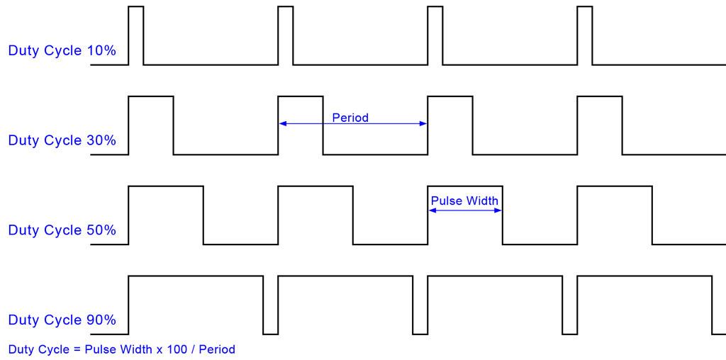
A duty cycle of ten percent would have a pulse width of ten percent, or it would be on for ten percent of the cycle and off for ninety percent of the cycle. The motor, then, would spin at ten percent of its full speed. Conversely, a cycle of ninety percent would have a pulse width of ninety percent, or it would be on for ninety percent of the cycle and off for ten percent of the cycle. The motor would spin at ninety percent of its full speed.
The 555 test circuit provides a duty cycle of fifty percent—it is on for half a cycle and off for half a cycle spinning the motor at half its full speed. It’s useful if you want to drive a motor directly without any additional circuitry such as a Snap Circuits motor or Lego Technic motor and only need one speed. I have tested the circuit with an erector set motor, but as soon as you put any kind of load on it, the 555 chip starts to heat up rather quickly so you’d need to add additional circuitry such as an H-bridge or TIP31 transistor.
In the following diagram you’ll notice that you can vary the resistance with the potentiometer, but the output duty cycle is always 50% and you’ll only notice a small change in the speed of the motor as the frequency of the square wave increases, but the small increase in motor speed isn’t very useful.

Some 555 timer circuits do allow for full PWM adjustment and thus the full range of variable motor speeds. The 555 test circuit simply demonstrates that you can use the 50% duty cycle output from pin 3 to spin a motor even if it is only at 50% full speed.
For a practical use of the 555 test circuit single speed motor driver, I decided to demonstrate how to build a simple magnetic stirrer.
Parts needed:
555 Timer IC (I used a KIA555p, but the NE555 will do just fine)
Erector set (Meccano) Bush Wheel
2 Erector set (Meccano) set screws
2 Neodymium Magnet - Disc, Grade N35, with Pressure Sensitive Adhesive Part # N35P500060PSAS
Snap Circuits Parts:
1 Base Grid (11” x 7.7”) # 6SC BG
1 Eight-Pin IC Socket # 6SC ?U8
1 0.02uF Capacitor # 6SC C1
1 Variable Resistor #6SC RV
1 Whistle Chip # 6SC WC
1 4.5 Volt Battery Holder # 6SC B3
1 Slide Switch # 6SC S1
1 Motor #6SC M4
1 Single Snap Conductor # 6SC 01
9 Conductor with 2-snaps # 6SC 02
5 Conductor with 3-snaps # 6SC 03
1 Conductor with 4-snaps # 6SC 04
1 Conductor with 5-snaps # 6SC 05
2 Conductor with 6-snaps # 6SC 05
Optiona Parts:
Jumper Wire 18" (Black) # 6SC J1
Jumper Wire 18" (Red) # 6SC J2


Since the axle on the Motor (M4) from the Snap Circuits Green set is much narrower than an Erector set axle, I had to use two set screws to center the Erector set bush wheel on the axle of the motor. Since the bush wheel is steel (with brass plating, I think) there’s no need to use the pressure sensitive adhesive to attach the neodymium magnets to the wheel. Originally I was going to use the plastic color wheel from the Snap Circuits Light set and two neodymium magnets from a magnetic key chain I took apart, but the first time I spun up the motor it spun up too fast and one of the magnets from the old key chain went flying (I still haven’t found it). The Erector set bush wheel is heavy enough to slow the motor down so that the centrifugal force doesn't overcome the 1.8 pounds of holding force of the neodymium magnets.
I like that the magnets have the adhesive (I’m sure this will come in handy in another project) because the peel off paper backing makes it easier to attach the magnets with the correct polarity to spin the magnetic stir bar. On one side of the bush wheel attach the magnet with the peel off paper facing down and on the opposite side of the wheel attach the magnet with the peel off paper facing up.
In the following video, I replaced the two 2 snap conductors attached to the motor with the red and black jumper wires so that I could position the motor under the 250ml beaker on my Bunsen burner stand. Because sound from the circuit was unnecessary for the video, I also removed the piezoelectric speaker, or Whistle Chip (WC).
Follow me on Twitter: @SteveSchuler20
NOTES:
Neodymium magnet source, Bunting Magnetics:
http://buymagnets.com/category/2/Rare-Earth-Magnets/
Disposable magnetic stir bar source, Dynalab:
http://www.dynalabcorp.com/literature_defaultpage.asp
If you order the stir bar samples, make sure you order the Dynalon Education Products catalog. On the back page of the 2012 catalog you could order the Free Science Gift Pack, which is how I got the 250ml beaker among other items such as a graduated cylinder and Azlon wash bottle.
Snap Circuits Light Manual


Comments