Banner
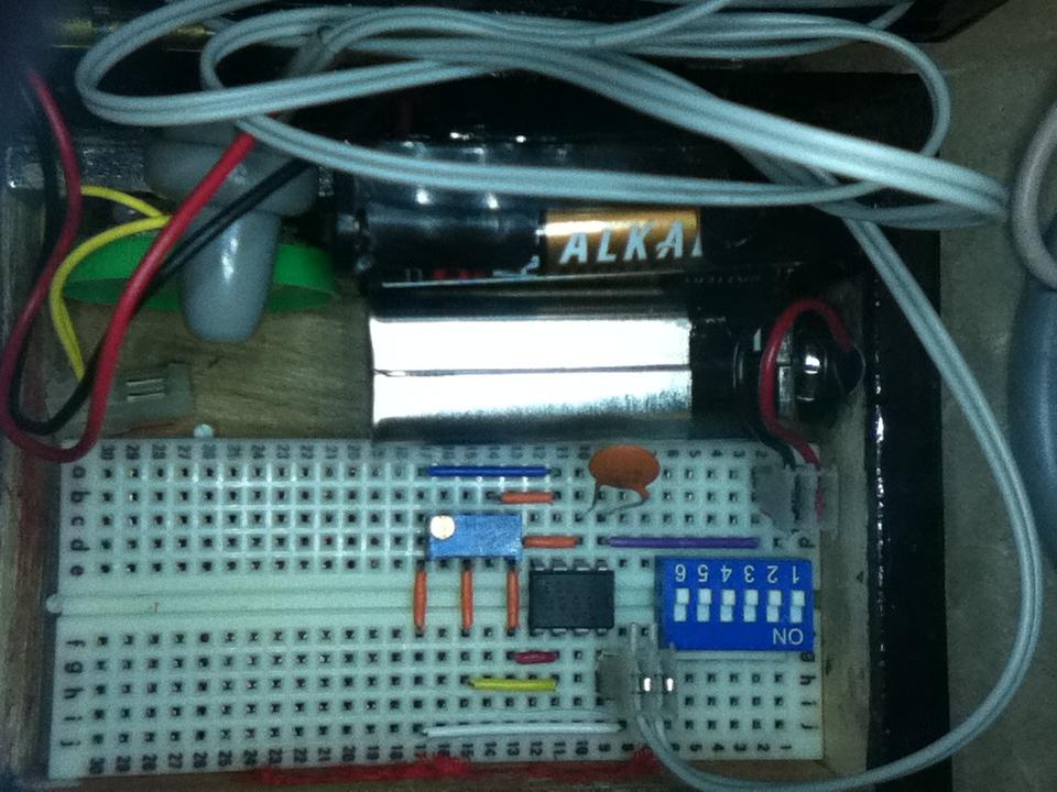
Variable Speed Fan With Snap Circuits, Kano Computer

In a previous How-To Guide I demonstrated how to blink a Snap Circuits LED with the Kano Computer...

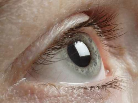
IUPUI researchers use stem cells to identify cellular processes related to glaucoma

INDIANAPOLIS -- Using stem cells derived from human skin cells, researchers led by Jason Meyer...
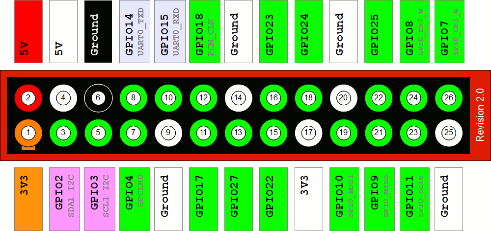
Pi Day 2016 Project

For Pi Day 2016, I’ll demonstrate how to flash a Snap Circuits LED with the Kano Computer (my...

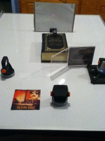
LIGO, Gravitational Waves, And Laser Interferometry

UPDATE: LIGO has detected gravitational waves. ...


Source

Dr. Tae, the skateboarding physicist, "Can Skateboarding Save Our Schools?" (Did I mention he’s a physicist AND a sk8r?)

Sir Ken Robinson’s “Do Schools Kill Creativity?” A stand-up set on education.

I did almost all of them when I was a kid, except superglue my fingers together. I had a few pocket knives but my favorite was the Swiss Army knife. This is what I use today to void product warranties:


Leatherman Juice XE6

Without further ado, Gever Tulley's "5 Dangerous Things You Should Let you Kids Do":

And here's 5 more things your should let you children do, according to Tulley:

I've lost count of how many computers I've built over the years, but I think it is safe to say that the Kano Computer was the easiest build ever. So simple a child could do it. Kano founders, Yonatan Raz-Fridman, Alex Klein, and Saul Klein, wanted to figure out what the next generation’s computer would be like, so they asked Micah, Saul’s seven-year-old son.
You can build a simple circuit using two 555 Timer ICs to create an H-bridge that will drive a single motor in forward or reverse. An H-bridge circuit is often used in robotics to reverse the polarity of a motor. For example, if the motor is spinning in the forward direction, the robot will move forward and when the polarity of the motor is reversed, the motor will spin in the opposite direction and the robot will move backward.

Follow me on Twitter: SteveSchuler20

The diagram of the circuit resembles the letter “H” where the motor is the cross-bar and four switches form the legs.

Play the video below to see how to solve the puzzle I posted last week:

The object actually appears as it is pictured. It is not an optical illusion. The image was not created using an “in camera” special effect (no special lighting, no filters other than the built-in infrared filter, no mirrors, or any other “in camera” special effect technique). The image has not been modified with digital photography editing software. The object was not taped, or glued, or otherwise fastened together. The object was created using a single piece of ordinary twenty pound bond computer printer paper and a pair of scissors. Are you able to solve the puzzle of how it was made?

A tone generator is a useful piece of test equipment used, for example, to test the frequency range of audio equipment such as your stereo or the external speakers for your iPod. A tone generator can also be used to tune a musical instrument such as a guitar. You can make a simple tone generator using a 555 Timer IC, a capacitor, potentiometer, speaker, and a power source (circuit pictured above). Here’s the schematic: