

Much of the genius of Georg Ohm is forgotten. He is remembered mostly as the scientist who defined the relationship between electrical resistance, electric force and electric current. Not only do writers generally ignore Georg Ohm's many other contributions to physics: they give an all-too-brief outline of Ohm's law and then move on. Thus they miss the opportunity to explain the simplicity of the physical reality and the elegance of the mathematics behind Ohm's Law.
Prior researchers had used only vague terms and inexact measurements for the way that electricity is opposed in its flow through conductors. Ohm showed for the first time how to relate electrical resistance R, current intensity I, and electromotive force E in an exact mathematical way, thus placing the matter on a sure scientific foundation. The maths is as simple as abc, that is to say, as simple as the algebraic expression a = bc. At this point, just about every writer proceeds to show the three ways of writing Ohm's law. In my view, this obscures the elegance of Ohm's single most important discovery, a defect which I hope to correct here.
Prior to Ohm's researches, experimenters who tried to establish a relationship between volts, current and resistance had varying success. The problem was that experimental results varied too much. The problem of variability was solved by Ohm. Starting from philosophical and physical basics he showed how the properties of the voltage source and of the measuring instruments were subject to variation between experimenters and between experiments. By excluding the sources of these variations, or by allowing for them in his calculations, he succeeded in establishing that the physical relationship between electrical pressure, electric current and resistance was beautifully and intuitively simple.
Georg Ohm correctly deduced that the reported experimental variability was due to factors inherent in the physics and construction of the voltaic pile and the galvanometer - of which more below - and that the variability was not due to physical processes in a conductor at constant temperature. He accordingly formulated the hypothesis that the resistance of any electric circuit or of any of its component parts is fixed by the physical properties of the materials used. He then demonstrated through philosophical argument and the physical reality of experiments that his hypothesis was correct: that it was a theory supported by evidence. Like so many new ideas in physics, his theory was at first generally rejected in academia. As ever more accurate experimental apparatus produced ever greater precision in the measurement of resistance there soon came a time when Ohm's theory was not just accepted: it was adopted as a law of physics.
How Ohm measured resistance
In Georg Ohm's day almost all electrical apparatus was purpose built by the experimenter or an assistant. The only item likely to be bought ready-made was the galvanometer. Today, the term 'galvanometer' is applied to many different forms of measuring instrument. In Ohm's day, the galvanometer consisted of one or more turns of wire surrounding what was effectively a small compass needle. The needle would be deflected in proportion to the current flowing through the wire. Ohm correctly deduced that galvanometers made by different people would use different lengths and compositions of wire and would hence exhibit different resistances. He showed that galvanometers made to a consistent specification would produce consistent results.
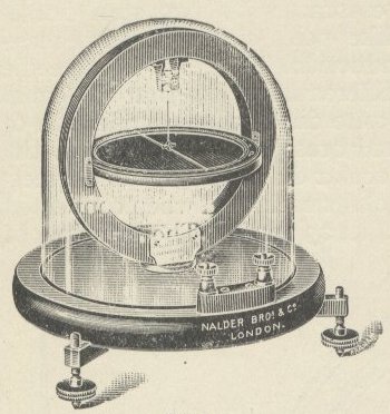
A galvanometer from the early 1900s.
The other major component used by experimenters was the voltaic pile, formerly Volta's pile, named after its inventor, Alessandro Volta. It was a vertical pile of pairs of zinc and copper with each pair separated by paper wet with sulfuric acid. Georg Ohm, no doubt building on the electrochemical theory of Theodor Grotthus, and working from the basic principles of electrostatics as then known, deduced that the pile would be subject to a reduced voltage due to the movement of chemical current carriers. That is to say, the positive and negative charge carriers would move within the fluid and tend to cluster where they meet the metal surface and thus tend to oppose by repulsion the flow of further carriers.
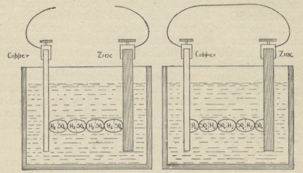
Chemicals in a cell split into charge carriers when the external circuit is complete.
(Grotthus, and Ohm after him, clearly envisioned these chemicals and ions as what we would today call molecules and ions.)
There are also chemical changes in the pile which are constantly changing its electrical characteristics. In modern terms we would say that the internal resistance of a battery is not a fixed quantity. Again, due to impurities in the metals, there are local variations of chemical action. To avoid the problem of the variability of voltage between different piles and different experiments with the same pile, Ohm used a different voltage source: the thermocouple. Thomas Johann Seebeck had demonstrated in 1821 that the application of a temperature gradient to the junction between two different metals caused a voltage to appear between the two junctions. Ohm made use of the fact that if the temperature gradient is held constant then the voltage is constant.
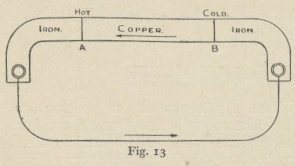
An example of a thermoelectric source.
Working now with consistent and easily replicated apparatus for the production and measurement of electrical forces, Ohm was able to demonstrate the facts about resistive circuits which we today take for granted. I will now step through Ohm's methods and proofs using modern English, but hoping to retain the essential accuracy of Ohm's original publication: Die galvanische kette, mathematisch (1827), translated into English, with many interesting footnotes by other now-famous scientists, as The galvanic circuit investigated mathematically (1891).
The flow of electricity from a voltage source, through a circuit and back to the source is assumed by convention to proceed from the positive to the negative terminal. However simple or complicated the external circuit, the number of energy carriers leaving the battery will equal the number returning to the battery, hence the flow of electric current through the source is identical to the flow through the entire circuit.
In a simple circuit having no parallel paths, it does not matter how many different sections of wire are joined together, or how thick they are or of what material. Nor does it matter in what order they appear in the circuit: the current flowing past all points in the circuit will be the same throughout.
If a voltage source is connected to a circuit consisting of a single uniform wire, then the voltage between the ends of the wire will be the same as the battery voltage. At a constant temperature, the current flowing in the wire is dependent solely on the physical properties of the wire and the voltage between its ends.
If the wire mentioned in the above statement is reduced to half its length while the voltage remains constant, the current will double. Conversely, if the wire is doubled in length, the current will be halved. If, instead of making a change in the wire, a second identical wire is connected across the voltage source in parallel with the first wire, the current in the second wire will equal the current in the first wire and so the current supplied by and passing through the source will be doubled.
The voltage is maximum at one end of a uniform wire, and zero at the other end. The current flowing past all points in the wire is constant. It follows that the voltage declines uniformly along the wire such that at the midpoint of the wire, the voltage measured with respect to the zero or negative terminal will be exactly half of the applied voltage.
Where a circuit is made up of two or more sections of wire of different diameter or composition, the voltage gradient will be uniform across each section but will not necessarily be uniform over the whole circuit. The voltage being constant, and the current being the same though all points in the circuit, it follows that the effect of a number of sections of different resistance connected in series can be replicated by a single wire of uniform composition and diameter made to a suitable length. (Ohm called this equivalent wire the 'reduced length' of the circuit. Today, we would simply state the total resistance of the circuit as a specific number of Ohms.)
The voltage at any point in a circuit in which a constant current is flowing can be calculated if the resistance of all components of the circuit are known. In the case of a uniform wire carrying a uniform current, the voltage between any two points can be calculated from the distance between those two points. (This observation forms the basis of the widely-used potentiometer, a device which picks off a specific voltage along a resistive element through which a current is flowing.)
The resistance of a wire or circuit is physically constant at constant temperature. Any variation in the current passing through it is due entirely to a variation in the applied voltage. Conversely, if the current through a section of a circuit or wire is varied, then the voltage measured across that section will also vary.
Given that the resistance of a conductor is constant at constant temperature, it is always found that when a voltage is applied between the ends of the conductor, the current caused to flow by that voltage is determined entirely by the resistance of the conductor.
The resistance of a conductor can be measured by determining what voltage will cause a specific current to flow, or by measuring the current which flows when a specific voltage is applied.
We now come to the elegance and simplicity of the physical reality of resistive circuits. To determine the value of a resistance in Ohms, simply apply a voltage source across the resistor. Now measure the voltage across the resistor and the current through it. There is no need to use a precision source of voltage or current: whatever the source of power, if voltage and current are measured at the same instant, then the resistance is equal to voltage divided by current in standardized units.
Suppose that a voltage of 1.5 Volts is measured with a current of 0.75 Amps. Intuition suggest that each half a volt pushes a quarter of an amp, hence 2 Volts would push 1 Amp. Now it just happens to be the case that 1.5 divided by 0.75 equal 2. As mentioned above, at this point, most writers on Ohm's law proceed to show the three ways of expressing the relationship between Volts, Amps and resistance. Thus, the simple elegance of Ohm's discovery is missed. If you determine the voltage across a resistance and the current through it, you can express the resistance as the force required to push each Amp through the resistance: the number of Volts per Amp. If the result is expressed as the Volts which would be required to cause 1 Amp to flow, then the resistance in Ohms is identical to that Voltage.
It is really that simple: the resistance of a circuit or component is equal to the number of Volts it would take to force 1 Amp through it. Hypothetically speaking. In the real world, components are quite sensitive to the amount of power that they are required to handle. Electrical power in a purely resistive circuit is equal to the Volts across a component multiplied by the amps passing through it. Hypothetically, if you take a typical 1/4 Watt resistor of 1000 Ohms and stick 1000 Volts across it, it will pass 1 Amp. Non-hypothetically, it will blacken, smell bad, and shatter. Big-time! It would be much better for the poor resistor, and mathematically elegant, to apply 1 Volt across it and prove its resistance value in Ohms by seeing a current flow of only 1 thousandth part of an Amp, that is: 1 milliamp.
If you can picture that resistance in Ohms is a number identical to the Volts needed to cause a current of 1 Amp to flow through the resistor, then you will better understand the simplicity of Ohm's law. Where E stands for electromotive force in Volts, I stands for the current induced to flow, in Amps, and R stands for the resistance in Ohms, then:
R = E / I
I = E / R
E = I x R
and in the special case where I = 1, R ≡ E
Now that you fully understand the Ohm - you do, don't you? - you are ready to build on that foundation so as to learn more of the art of electrical and electronic engineering. It is indeed an art, and since it is founded on Ohm's discoveries, it is perfectly apt to say that Ohm is where the art is.
Ohm's legacy
Within less than 80 years of Ohm's findings, distributed electrical power - mains electricity - had become common and various kinds of meter were being manufactured for the newly needed electrical engineers and technicians. Compared to the spread out spaghetti wiring on a lab bench they were indeed what the manufacturers claimed: compact.
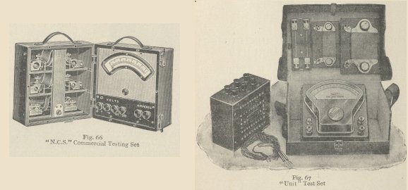
Some 'compact' test meters from the early 1900s.
These test sets have a selection of resistors for use as shunts. The use of an ammeter - Amp meter - shunt follows directly from Ohm's finding that a low value resistance will divert much of the current past a galvanometer, but will not affect its proportional response to current variations in the circuit of which the meter is a part.
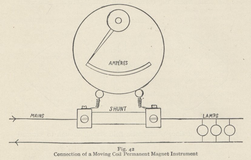
How a meter is wired across a shunt.
(The shunt is of substantially lower resistance then the meter, so although the combination can be used to measure a heavy current, the meter itself does not have to carry that current. This is important as the sensitivity of a meter is closely connected to the delicacy of its construction. The fine wire used in the moving coil of most analog meters would be so much fuse wire to a high current.
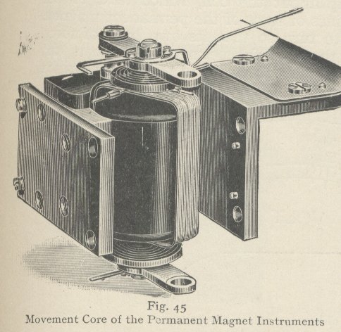
An early design of moving coil meter.
(Modern meters follow the same basic design but tend to be smaller and / or more sensitive.)
Thanks to Ohm's researches into the physics of electric flow, we now take for granted a large number of well known facts, just a few of which are mentioned below.
An electric current when presented with alternate paths will divide so that the bulk of the current passes through the path of least resistance. This means that the total resistance of a number of resistances in parallel will always be less than the value of the least resistance. It also means that if you let yourself become the path of least resistance for high voltage electricity then you are in danger of death. Be warned!
Be also warned about the Christmas / festive / fairy lights effect, which Georg Ohm very cleverly proved long before the invention of the electric lamp. If a circuit is broken anywhere along its length, then the whole source voltage appears across the open ends. In the case of a chain of mains operated fairy lights, even though they are commonly low voltage bulbs, the whole mains voltage of 110 or 220 Volts will appear at the open socket or broken wire ends ready to kill you if you do not unplug the lights before attempting a repair.
When a number of cells are to be connected as a power source for a circuit, the fact that each cell has an internal resistance must be kept in mind. If the external circuit has a high resistance, then a higher voltage is provided by a number of cells in series. Conversely, if the circuit has a low resistance, then cells in parallel will best match the circuit demand for current, since cells in parallel provide the same voltage but more current. Cells in parallel have less total resistance than any one cell. This matching of multi-cell arrangements to suit circuit demands is known today as impedance matching. Impedance matching is of vital importance in many applications of electrical and electronic engineering.
Ohm's demonstrations of a voltage gradient along a wire led to the invention of the slide wire potentiometer, the forerunner of every kind of potentiometer - one form of variable resistor.
The slide wire is used with a variant of the most versatile and easy to understand scientific instrument: the Wheatstone bridge. It is used in its original form for the precise measurement of resistance, but is adaptable to many other purposes. It can even be used as an 'electrical slide rule'. Perhaps every Ohm should have one? Perhaps not.
More soon.
---------------------------------------------------
Note: the images used here are from a set of books - 'Electricity', 6 volumes - published in or about 1914 and now in the public domain.


Comments